Intel386™ EX EMBEDDED MICROPROCESSOR USER’S MANUAL
15-2
The RAS#-only method requires that the DRAM controller activate its RAS# signal when the
RCU activates its REFRESH# signal. This causes the controller to drive the refresh address gen-
erated by the RCU onto the DRAM address inputs, refreshing the specified DRAM row. With this
method, the controller need not assert the CAS# signal whenever the REFRESH# signal is active.
The CAS#-before-RAS# method requires that the DRAM device contain an internal counter to
determine the DRAM row addresses. To perform a refresh cycle using the CAS#-before-RAS#
method, the controller must generate a CAS# signal followed by a RAS# signal when the RCU
activates its REFRESH# signal. With this method, the DRAM device generates its own refresh
addresses and the RCU provides the REFRESH# signal.
If the CS6#/REFRESH# pin is being used for its CS6# function, another way of identifying a re-
fresh cycle is to look at the states of the bus status signals, M/IO#, D/C# and W/R#, (shown in
Table 6-2 on page 6-5) and the byte-enable signals (BHE# and BLE#). M/IO# and D/C# are high,
W/R# is low, and both BHE# and BLE# are inactive during a refresh cycle. These signals can be
used by the DRAM controller to initiate a DRAM refresh cycle.
15.2 REFRESH CONTROL UNIT OVERVIEW
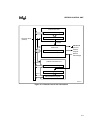
The RCU includes an interval timer unit, a control unit, and an address generation unit (Figure
15-1). The interval timer unit uses a refresh clock interval register and a 10-bit interval counter
to create a periodic signal (timeout). The control unit uses this signal to initiate periodic refresh
requests. The address generation unit uses a refresh base address register and a 13-bit address
counter to generate DRAM refresh addresses. The DRAM device can use these addresses as row
addresses during RAS-only refresh cycles. Each time the interval timer unit times out, a new re-
fresh address is generated.


