


11-25
ASYNCHRONOUS SERIAL I/O UNIT
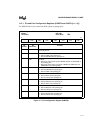
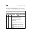
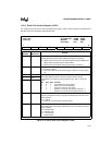
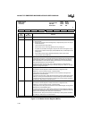
11.3.6 Serial Line Control Register (LCR
n
)
Use LCRn to provide access to the multiplexed registers, send a break condition, and determine
the data frame for receptions and transmissions.
Figure 11-15. Serial Line Control Register (LCR
n
)
Serial Line Control
LCR0, LCR1
(read/write)
Expanded Addr:
ISA Addr:
Reset State:
LCR0 LCR1
F4FBH F8FBH
03FBH 02FBH
00H 00H
7 0
DLAB SB SP EPS PEN STB WLS1 WLS0
Bit
Number
Bit
Mnemonic
Function
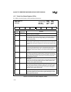
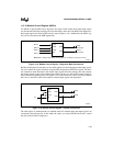
7 DLAB Divisor Latch Access Bit:
This bit determines which of the multiplexed registers is accessed.
0 = Allows access to the receiver and transmit buffer registers (RBR
n
and
TBR
n
) and the interrupt enable register (IER
n
).
1 = Allows access to the divisor latch registers (DLL
n
and DLH
n
).
6 SB Set Break:
0 = No effect on TXD
n
.
1 = Forces the TXD
n
pin to the spacing (logic 0) state for as long as bit is
set.
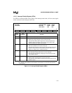
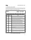
5 SP Sticky Parity, Even Parity Select, and Parity Enable:
These bits determine whether the control logic produces (during
transmission) or checks for (during reception) even, odd, no, or forced
parity.
SP EPS PEN Function
X X 0 parity disabled (no parity option)
0 0 1 produce or check for odd parity
0 1 1 produce or check for even parity
1 0 1 produce or check for forced parity (parity bit = 1)
1 1 1 produce or check for forced parity (parity bit = 0)
4EPS
3 PEN
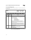
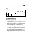
2 STB Stop Bits:
This bit specifies the number of stop bits transmitted and received in each
serial character.
0 = 1 stop bit
1 = 2 stop bits (1.5 stop bits for 5-bit characters)
1–0 WLS1:0 Word Length Select:
These bits specify the number of data bits in each transmitted or received
serial character.
00 = 5-bit character
01 = 6-bit character
10 = 7-bit character
11 = 8-bit character