


6-35
BUS INTERFACE UNIT
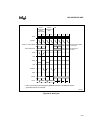
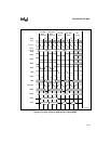
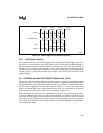
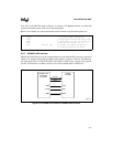
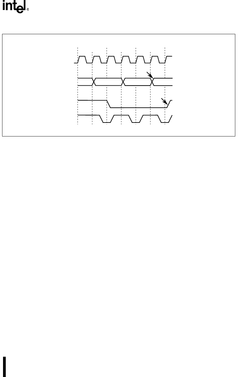
Figure 6-14. LOCK# Signal During Address Pipelining
6.4.3 LOCK# Signal Duration
The maximum duration of the LOCK# signal affects the maximum HOLD request latency be-
cause HOLD is recognized only after LOCK# goes inactive. The duration of LOCK# depends on
the instruction being executed and the number of wait states per cycle. The longest duration of
LOCK# is 9 bus cycles plus approximately 15 clocks. This occurs when an interrupt (hardware
or software) occurs and the processor performs a Locked read of the gate in the interrupt descrip-
tor table (8 bytes), a read of the target descriptor (8 bytes), and a write of the accessed bit in the
target descriptor.
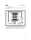
6.5 EXTERNAL BUS MASTER SUPPORT (USING HOLD, HLDA)
The processor provides internal arbitration logic that supports a protocol for transferring control
of the processor bus to an external bus master. This protocol is implemented through the HOLD
input and the HLDA output. The internal arbitration logic of the processor consists of a bus arbi-
ter. This arbiter supports the core and four other bus masters, i.e. external bus master using
HOLD, two internal DMA Units and the Refresh Control Unit. For a description of the protocol
of the internal bus arbiter, refer to “Bus Control Arbitration” on page 12-9.
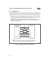
When the internal bus arbiter receives a request through one of its four possible request signals,
it asserts the HOLD signal to the core. The core then completes its current nonlocked bus cycle
and asserts its HLDA signal, thus informing the arbiter that control of the bus can now be turned
over to the requester.The arbiter then asserts its appropriate acknowledge signal to the requester.
For example, if an external bus master requests the bus using the HOLD input pin, then the arbiter
asserts the HLDA output.
A2489-02
LOCK#
CLKOUT
Unlocked
Bus Cycle
Locked
Bus Cycle
Locked
Bus Cycle
BLE#, BHE#, A25:1
Unlocked
Bus Cycle
LOCK Deasserted
Address Asserted
READY#