


Intel386™ EX EMBEDDED MICROPROCESSOR USER’S MANUAL
2-4
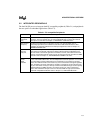
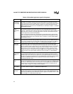
Table 2-2. Embedded Application-specific Peripherals
Name Description
System
Management
Mode (SMM)
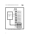
The Intel386 EX processor provides a mechanism for system management with a
combination of hardware and CPU microcode enhancements. An externally generated
system management interrupt (SMI#) allows the execution of system-wide routines that are
independent and transparent to the operating system. The system management mode
(SMM) architectural extensions to the Intel386 CPU are described in Chapter 7, “SYSTEM
MANAGEMENT MODE.”
Clock and
Power
Management
Unit
An external clock source provides the input frequency. The clock and power management
unit generates separate internal clock signals for core and peripherals (half the input
frequency), divides the internal clock by two for baud clock inputs to the SIO and SSIO, and
divides the internal clock by a programmable divisor to provide a prescaled clock signal
(various frequencies) for the TCU and SSIO.
Power management provides idle and powerdown modes (idle stops the CPU clock but
leaves the peripheral clocks running; powerdown stops both CPU and peripheral clocks).
An external clockout signal is also provided. Refer to Chapter 8, “CLOCK AND POWER
MANAGEMENT UNIT.”
Synchronous
Serial I/O
(SSIO) unit
Provides simultaneous, bidirectional high speed serial I/O. Consists of a transmit channel, a
receive channel, and a baud rate generator. Built-in protocols are not included, because
these can be emulated using the CPU. SSIO interrupts can be connected to the DMA unit
for high-speed transfers. Refer to Chapter 13, “SYNCHRONOUS SERIAL I/O UNIT.”
Chip-select
Unit (CSU)
Programmable, eight-channel CSU allows direct access to up to eight devices. Each
channel can operate in 16- or 8-bit bus mode and can generate up to 31 wait states. The
CSU can interface with the fastest memory or the slowest peripheral device. The minimum
address block for memory address-configured channels is 2 Kbytes. The size of these
address blocks can be increased by powers of 2 Kbytes for memory addresses and by
multiples of 2 bytes for I/O addresses. Supports SMM memory addressing and provides
ready generation and programmable wait states. Refer to Chapter 14, “CHIP-SELECT
UNIT.”
Refresh
Control Unit
(RCU)
Provides a means to generate periodic refresh requests and refresh addresses. Consists of
a programmable interval timer unit, a control unit, and an address generation unit. Bus
arbitration logic ensures that refresh requests have the highest priority. The refresh control
unit (RCU) is provided for applications that use DRAMs with a simple EPLD-based DRAM
controller or PSRAMs that do not need a separate controller. Refer to Chapter 15,
“REFRESH CONTROL UNIT.”
Parallel I/O
Ports
Three I/O ports facilitate data transfer between the processor and surrounding system
circuitry. The Intel386 EX processor is unique in that several functions are multiplexed with
each other or with I/O ports. This ensures maximum use of available pins and maintains a
small package. Each multiplexed pin is individually programmable for peripheral or I/O
function. Refer to Chapter 16, “INPUT/OUTPUT PORTS.”
Watchdog
Timer (WDT)
Unit
When enabled, the WDT functions as a general purpose 32-bit timer, a software timer, or a
bus monitor. Refer to Chapter 17, “WATCHDOG TIMER UNIT.”
JTAG Test-
logic Unit
The test-logic unit simplifies board-level testing. Consists of a test access port and a
boundary-scan register. Fully compliant with Standard 1149.1–1990,
IEEE Standard Test
Access Port and Boundary-Scan Architecture
and its supplement, Standard 1149.1a–1993.
Refer to Chapter 18, “JTAG TEST-LOGIC UNIT.”