


Intel386™ EX EMBEDDED MICROPROCESSOR USER’S MANUAL
12-6
data bus, depending on the transfer direction. Since the requester is selected via the DACKn# sig-
nal the requester address is not meaningful in a fly-by mode transfer.
Support logic (either external or built in to the I/O device) must be designed to monitor the
DACKn# signal and accordingly generate the correct control signals to the I/O device, since all
processor signals are used to access memory. This means that if it is an I/O to memory transfer,
this logic generates an I/O read cycle and the processor generates the memory write cycle. If it is
a memory to I/O transfer, the logic generates an I/O write cycle and the processor generates the
memory read cycle. This way the data is driven by the I/O device and latched by the memory de-
vice during an I/O to memory transfer, and driven by the memory device and latched by the I/O
device during a memory to I/O transfer.
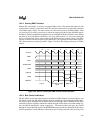
12.2.2.2 Two-Cycle Mode
The two-cycle option first fills the four-byte temporary buffer with data from the source, then
writes that data to the destination. This method allows transfers between any combination of
memory and I/O with any combination of data path widths (8- or 16-bit). The amount of data and
the data bus widths determine the number of bus cycles required to transfer data. For example, it
takes six bus cycles to transfer four bytes of data from an 8-bit source to a 16-bit destination: four
read cycles to fill the temporary buffer from the 8-bit source, and two write cycles to transfer the
data to the 16-bit destination.
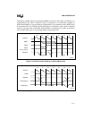
A buffer transfer can complete, be terminated, or be suspended before the temporary buffer is
filled from the source. If the buffer transfer completes or is terminated before the temporary buff-
er is filled, the DMA writes the partial data to the destination. When a requester suspends a buffer
transfer, the contents of the partially filled temporary buffer are stored until the transfer is restart-
ed. At this point, the DMA performs read cycles until the buffer is full, then performs write cycles
to transfer the data to the destination.
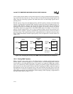
12.2.2.3 Programmable DMA Transfer Direction
The relationship between Requester, Target, Source, and Destination is determined by the pro-
grammable DMA transfer direction. The transfer directions are defined as Write, Read, or Verify.
The following table describes which operations are being performed by the Requester and Target
for each transfer direction. In this table, the device being read is the Source, and the device being
written is the Destination. The Verify cycle is used to perform a data read only. No write cycle is
indicated or assumed in a Verify cycle. The Verify cycle is useful for validating block fill opera-
tions. An external comparator must be provided to do any comparisons on the data read.
A special case not indicated in this table is when the Requester is neither the Source nor Destina-
tion. One example of this case would be when the DMA is being used to transfer data from one
memory or I/O location to another, and one of the timer outputs is being used to initiate that trans-
fer. In this case, the timer output would be selected as the DMA request source (using the
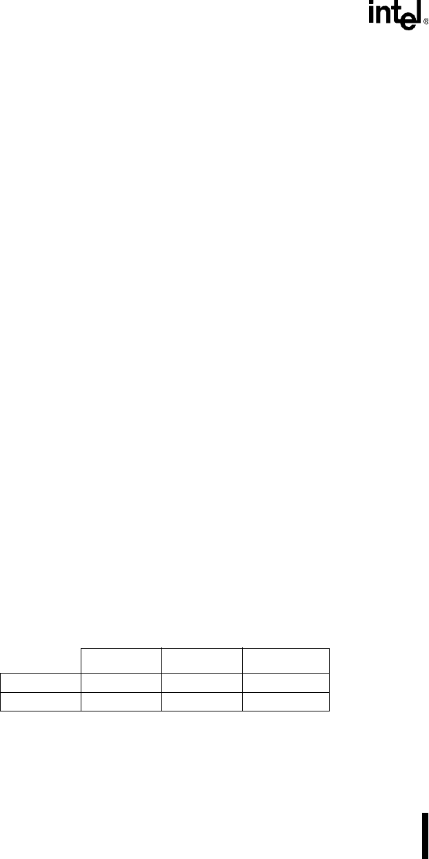
Table 12-2. Operations Performed During Transfer
Read Write Verify
Requester Read Write Read
Target Write Read Read