Intel386™ EX EMBEDDED PROCESSOR USER’S MANUAL
10-2
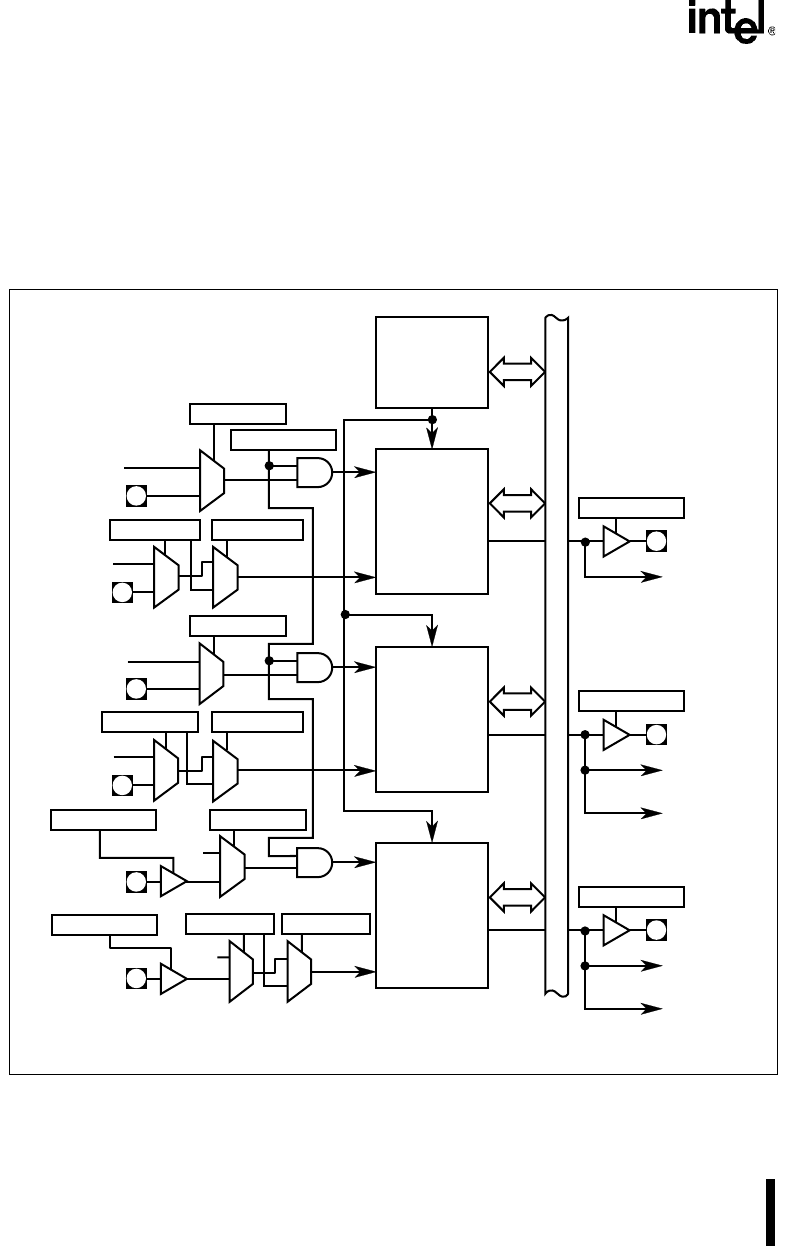
Therefore, the OUTn signals can drive external devices, generate interrupt
requests, initiate DMA transactions or combinations of the three.
Each counter operates independently. Six different counting modes are available and two count
formats: binary (16 bits) or BCD (4 decades). Each operating mode allows you to program the
counter with an initial count and to change this value “on the fly.” You can determine the count
and status of each counter without disturbing its current operation.
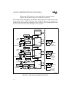
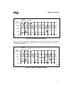
Figure 10-1. Timer/Counter Unit Signal Connections
OUT0
OUT1
CLKIN0
0
1
PSCLK
TMRCLK0
0
1
V
CC
TMRGATE0
0
1
TMRCLK1
0
1
TMRGATE1
0
1
TMRCLK2
0
1
TMRGATE2
GATE0
CLKIN1
GATE1
CLKIN2
GATE2
OUT2
Control Logic
A2317-02
TMRCFG.5
TMRCFG.4
TMRCFG.3
TMRCFG.2
TMRCFG.1
TMRCFG.0
TMRCFG.7
PINCFG.5
TMROUT2
To ICU
(Slave IR3)
To DMA
Ch1 MUX
P3CFG.1
To ICU
(Slave IR2)
To DMA
Ch0 MUX
TMROUT1
P3CFG.0
To ICU
(Master IR0)
TMROUT0
S
y
s
t
e
m
B
u
s
V
CC
V
CC
PSCLK
PSCLK
PINCFG.5
PINCFG.5
TMRCFG.6
0
1
TMRCFG.6
0
1
0
1
TMRCFG.6


