Intel386™ EX EMBEDDED PROCESSOR USER’S MANUAL
10-20
10.3 REGISTER DEFINITIONS
The following sections describe how to configure a counter’s input and output signals, initialize
a counter for a specific operating mode and count format, write count values to a counter, and
read a counter’s status and count.
10.3.1 Configuring the Input and Output Signals
Each counter is driven by a clock pulse on its CLKINn input. You can connect each counter’s
CLKINn input to either its timer clock (TMRCLKn) pin or the prescaled clock (PSCLK) signal.
The counters can handle up to 1/2 the processor clock (CLK2/4) input frequency but only up to
a maximum of 8 MHz (CLKINn frequency can never be more than 8 MHz). PSCLK is an internal
signal that is a prescale value of the processor’s internal clock. The frequency of PSCLK is pro-
grammable. See “Controlling the PSCLK Frequency” on page 8-7.
The GATEn signals of the counters can be controlled through hardware or software, as described
in the next two sections.
10.3.1.1 Hardware Control of GATE
n
You can connect each counter’s GATEn signal to:
• Its timer gate (TMRGATEn) pin
• V
CC
Hardware (through a pin or V
CC
) control of the GATEn requires that the SWGTEN bit in the
TMRCFG register be reset.
10.3.1.2 Software Control of GATE
n
You can also use the TMRCFG register to drive GATEn high or low through register bits. The
SWGTEN and GTnCON bits are used to control the GATEn signal. If SWGTEN is set, then the
value of the GTnCON bit causes the GATEn input of the counter to be driven to the corresponding
voltage level.
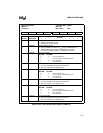
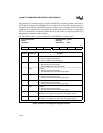
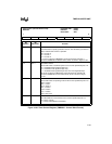
The timer configuration register (TMRCFG) enables the counter’s CLKINn signals and deter-
mines each counter’s CLKINn and GATEn signal connections or logical value (Figure 10-22).
Table 10-4. GATE
n
Connection Options
SWGTEN GT
n
CON
GATE
n
connection
00 V
CC
0 1 TMRGATE
n
10 0
(Gate
n
is OFF)
11 1
(Gate
n
is ON)


