6-11
BUS INTERFACE UNIT
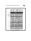
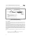
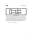
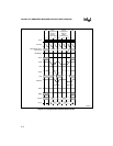
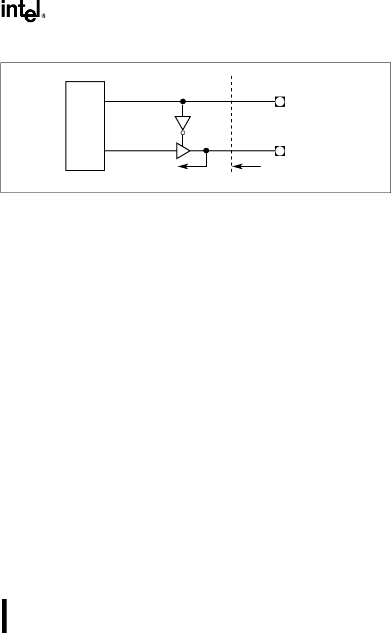
Figure 6-3. Ready Logic
When an internal cycle occurs, the LBA# signal becomes active in Phase 1 of the first T2 state.
It then stays active until the rising edge of PH1 of the first T2, T2i or T2P state of the next bus
cycle that requires external READY# to terminate the bus cycle. For example, the processor may
start an internal bus cycle, go through a few idle states, perform another internal cycle, then a cy-
cle in which the Chip-select Unit generates READY#, run through a few more idle states and then
finally do a cycle in which READY# needs to be generated by external logic. LBA# goes active
in the first T2 state of the first internal cycle, and stay active through the next two cycles (even
during all the idle states in between) and go inactive at the rising edge of PH1 in the first T2, T2i
or T2P state of the final cycle (the one that requires an external READY# to terminate).
NOTE
LBA# is deasserted during HOLD cycles.
A2485-01
Bus
Unit
READY#
LBA#
Chip Boundary
To Internal Units


