


Intel386™ EX EMBEDDED PROCESSOR USER’S MANUAL
10-32
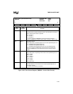
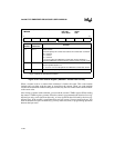
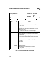
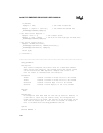
Figure 10-30. Timer
n
Register (TMR
n
– Status Format)
Timer
n
(Status Format)
TMR
n
(
n
= 0–2)
Expanded Addr:
ISA Addr:
Reset State:
F040H, F041H
F042H
0040H, 0041H
0042H
XXH
7 0
OUTPUT NULCNT RW1 RW0 M2 M1 M0 CNTFMT
Bit
Number
Bit
Mnemonic
Function
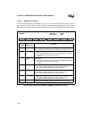
7 OUTPUT Output Status:
This bit indicates the current state of the counter’s output signal.
0 = OUT
n
is low
1 = OUT
n
is high
6 NULCNT Count Status:
This bit indicates whether the latest count written to the counter has
been loaded. Some modes require a gate-trigger before the counter
loads new count values.
0 = the latest count written to the counter has been loaded
1 = a count has been written to the counter but has not yet been loaded
5–4 RW1:0 Read/Write Select Status:
These bits indicate the counter’s programmed read/write selection.
00 = Never occurs
01 = read/write least-significant byte only
10 = read/write most-significant byte only
11 = read/write least-significant byte first, then most-significant byte
3–1 M2:0 Mode Status:
These bits indicate the counter’s programmed operating mode.
000 = mode 0
001 = mode 1
X10 = mode 2
X11 = mode 3
100 = mode 4
101 = mode 5
X is a don’t care.
0 CNTFMT Counter Format Status:
This bit indicates the counter’s programmed count format.
0 = binary (16 bits)
1 = binary coded decimal (4 decades)