8-3
CLOCK AND POWER MANAGEMENT UNIT
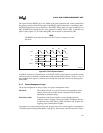
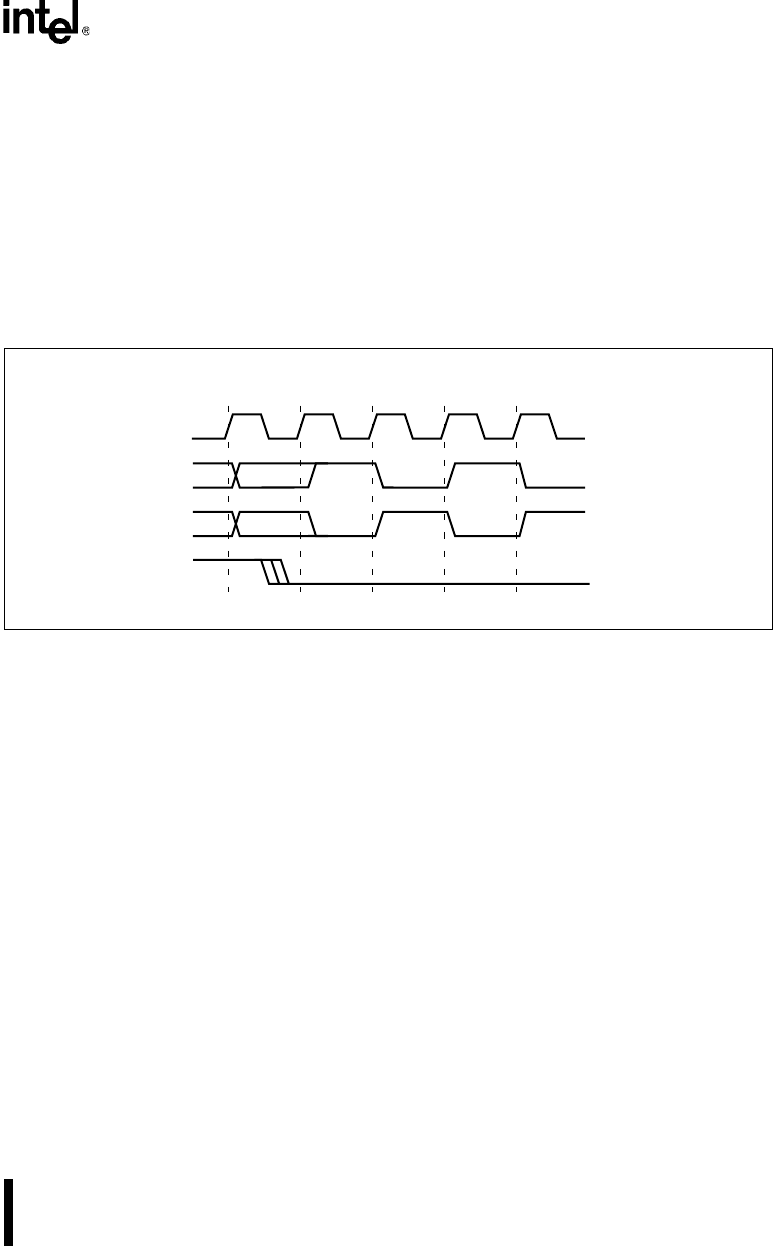
The signal from the RESET pin is also routed to the clock generation unit, which synchronizes
the processor clock with the falling edge of the RESET signal and provides a synchronous inter-
nal RESET signal to the rest of the device. The RESET falling edge can occur in either PH1 or
PH2. If RESET falls during PH1, the clock generation circuitry inserts a PH2, so that the next
phase is PH1 (Figure 8-2). If it falls during PH2, the next phase is automatically PH1.
NOTE
The RESET signal must be high for 16 CLK2 cycles to properly reset the
processor.
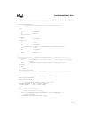
Figure 8-2. Clock Synchronization
In addition to internal synchronization, a CLKOUT (PH1P) clock output is provided to enable
external circuitry to maintain synchronization with the Intel386 EX processor. Since it is one of
the peripheral clock signals, it remains active during idle mode, but is driven low during power-
down mode.
8.1.2 Power Management Logic
The power management circuitry provides two power management modes:
Idle Mode Idle mode freezes the core clocks, but leaves the peripheral clocks
running. Idle mode can reduce power consumption by about half,
depending on peripheral usage.
Powerdown mode Powerdown mode freezes both the core and peripheral clocks,
reducing current to leakage current (microamps). Peripherals that are
clocked externally (SIO, Timers, SSIO) continue to run. If inputs are
toggling, power consumption is higher.
To prepare for a power management mode, program the power control register as described in
“Controlling Power Management Modes” on page 8-8, then execute a HALT instruction. The de-
A2467-01
CLK2
PH2
? ? ? PH2 PH1
PH1
RESET
PH2


