9-29
INTERRUPT CONTROL UNIT
9.4 DESIGN CONSIDERATIONS
The following sections discuss some design considerations.
9.4.1 Interrupt Acknowledge Cycle
When the core receives an interrupt request from the master, it completes the instruction in
progress and any succeeding locked instructions, then initiates an interrupt acknowledge cycle.
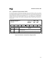
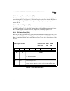
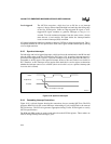
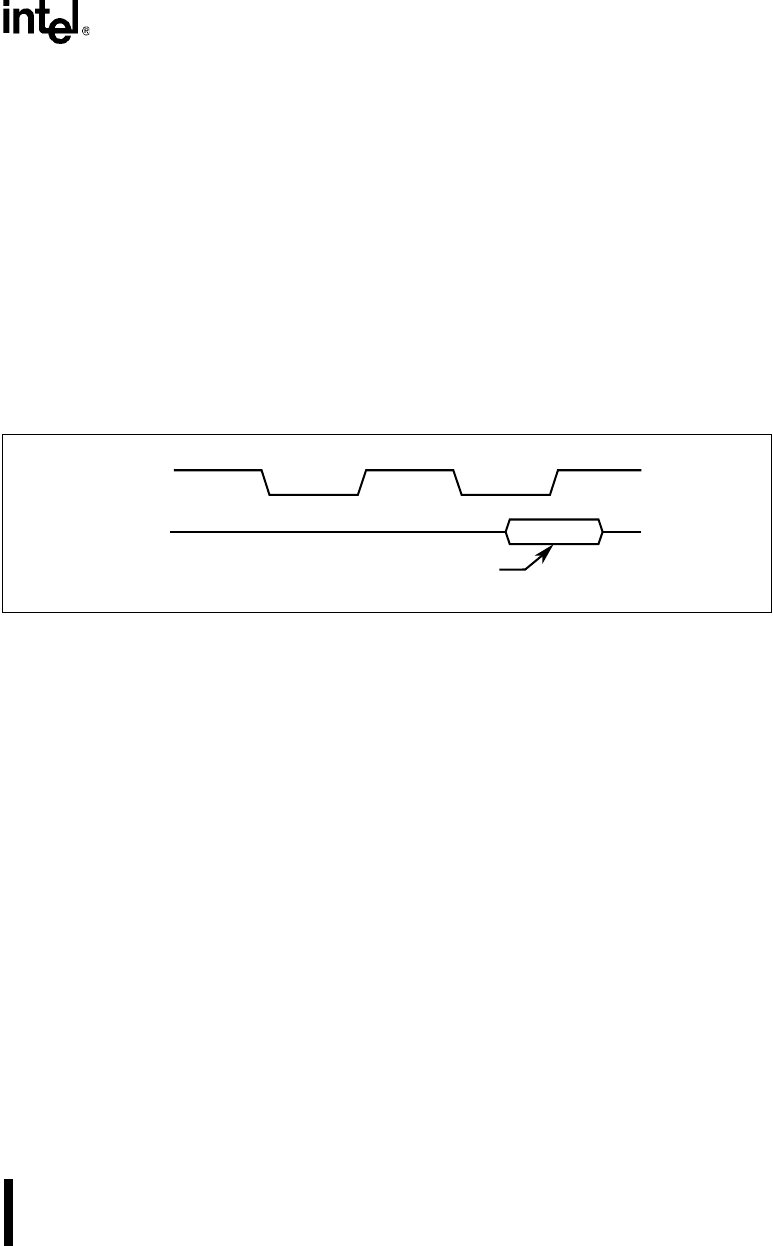
The interrupt acknowledge cycle generates an internal interrupt acknowledge (INTA#) signal that
consists of two locked pulses (Figure 9-17). This INTA# signal is connected to the internal
82C59A interrupt acknowledge inputs. On the falling edge of the second INTA#, the 82C59A sets
its interrupt in-service bit. It then clears its interrupt pending bit on the rising edge of the second
INTA#. On the second INTA# falling edge, the addressed 82C59A (determined by the master’s
cascade signals) also drives the interrupt vector number on the data bus.
Figure 9-17. Interrupt Acknowledge Cycle
9.4.2 Interrupt Detection
The processing of an interrupt begins with the assertion of an interrupt request at one of the IR
signals. During system initialization, you can program the IR signals, as a group, to be either edge
or level triggered (using ICW1 described in Figure 9-8).
Edge triggered The 82C59A recognizes a rising edge transition on an IR signal as an
interrupt request. A device requesting service must maintain a high state
on an IR signal until after the falling edge of the first INTA# pulse. You
can reset the edge-detection circuit during initialization of the 82C59A
or by deasserting the IR signal. To reset the edge-detection circuit
properly, the interrupt source must hold the IR line low for a minimum
time of 10ns.
A2430-01
INTA#
Data Bus
Vector Number
valid


