15-13
REFRESH CONTROL UNIT
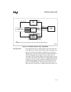
Figure 15-7. RAS# Only Refresh Logic: Paged Mode
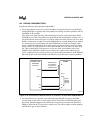
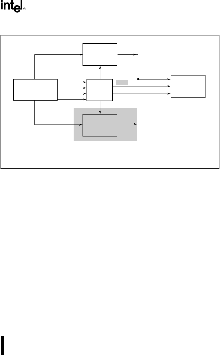
Non-page Mode In non-paged mode, the row address buffer can be connected to the
lower address lines and the column address buffer to the upper lines.
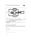
Figure 15-8 illustrates the hardware configuration for non-paged
DRAM accesses. The lines and buffer that are enabled in this type of
refresh are highlighted in the figure. The lower address bits are
connected to the Row Address Buffer and the upper address bits are
connected to the Column Address Buffer. As in Page Mode, the PLD
recognizes a refresh request by sampling both BHE# and BLE# (they
are both inactive during a refresh cycle), or by detecting an active
signal on the REFRESH# pin. The buffer and lines that are active
during this type of refresh have a shaded background in Figure 15-8.
Intel386™ EX
Embedded Processor
Row
Address
Buffer
PLD
Upper Address
Row
Address
Paged
DRAM
Column
Address
Address
Lower Address
OE_ROW#
OE_COL#
RAS#
CAS#
BHE#
BLE#
A3264-02
Column
Address
Buffer
CS
n
#
REFRESH#
Note:
A single mux can be used in place of the row and column address buffers.


