14-13
CHIP-SELECT UNIT
14.4 REGISTER DEFINITIONS
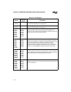
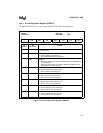
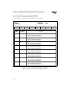
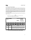
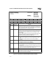
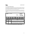
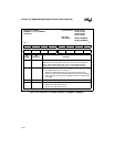
Table 14-1 and Table 14-2 list the signals and registers associated with the chip-select unit. There
are seven general-purpose chip-select channels (CSn) and one upper chip-select channel (UCS).
Upon reset, the UCS is enabled with the entire 64 Mbyte memory address space as its address
block. The UCS can be used to select a memory device at the top of the memory address space
so that the processor can fetch the first instruction from address 3FFFFF0H after reset.
Table 14-1. CSU Signals
Signal
Device Pin or Internal
Signal
Description
CS6:0#
UCS#
Device pins
(output)
Chip-select Signals:
Indicates that the memory or I/O address that the
processor is accessing is in channel
n
’s active address
region.


