Fixed-Point Interrupts and Exceptions 5-7
5.5 General Interrupt Handling Registers
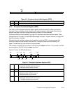
The general interrupt handling registers are the Machine State Register (MSR), SRR0–SRR3, the
Exception Vector Prefix Register (EVPR), the Exception Syndrome Register (ESR), and the Data
Exception Address Register (DEAR).
5.5.1 Machine State Register (MSR)
The MSR is a 32-bit register that holds the current context of the PPC405. When a noncritical
interrupt is taken, the MSR contents are written to SRR1; when a critical interrupt is taken, the MSR
contents are written to SRR3. When an rfi or rfci instruction executes, the contents of the MSR are
read from SRR1 or SRR3, respectively.
Programming Note: The rfi and rfci instructions can alter reserved MSR fields.
The MSR contents can be read into a general purpose register (GPRs) using an mfmsr instruction.
The contents of a GPR can be written to the MSR using an mtmsr instruction. The MSR[EE] bit may
be set/cleared atomically using the wrtee or wrteei instructions.
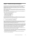
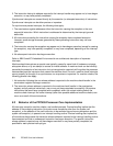
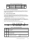
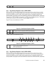
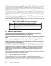
Figure 5-1 shows the MSR bit definitions and describes the function of each bit
.
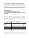
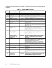
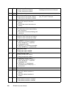
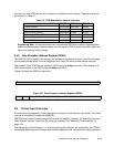
0x1200 Instruction TLB miss Synchronous precise Noncritical 5-25
0x2000 Debug—BT, DAC, DVC,
IAC, IC, TIE
Synchronous precise Critical 5-26
Debug—EXC, UDE Asynchronous precise Critical
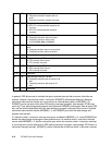
Figure 5-1. Machine State Register (MSR)
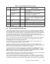
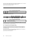
0:5 Reserved
6 AP Auxiliary Processor Available
0 APU not available.
1 APU available.
7:11
Reserved
12 APE APU Exception Enable
0 APU exception disabled.
1 APU exception enabled.
13 WE Wait State Enable
0 The processor is not in the wait state.
1 The processor is in the wait state.
If MSR[WE] = 1, the processor remains in
the wait state until an interrupt is taken, a
reset occurs, or an external debug tool
clears WE.
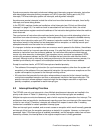
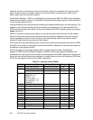
Table 5-2. Interrupt Vector Offsets (continued)
Offset Interrupt Type Interrupt Class Category Page
0 567 11 12 13 14 15 16 17 18 19 20 21 22 23 24 25 26 27 28 31
DE
CE
EE
IR
WE
PR
DRME
FP
FE0
FE1
DWE
AP
APE


