


Timer Facilities 6-7
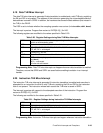
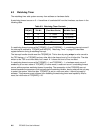
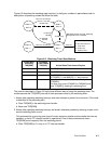
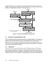
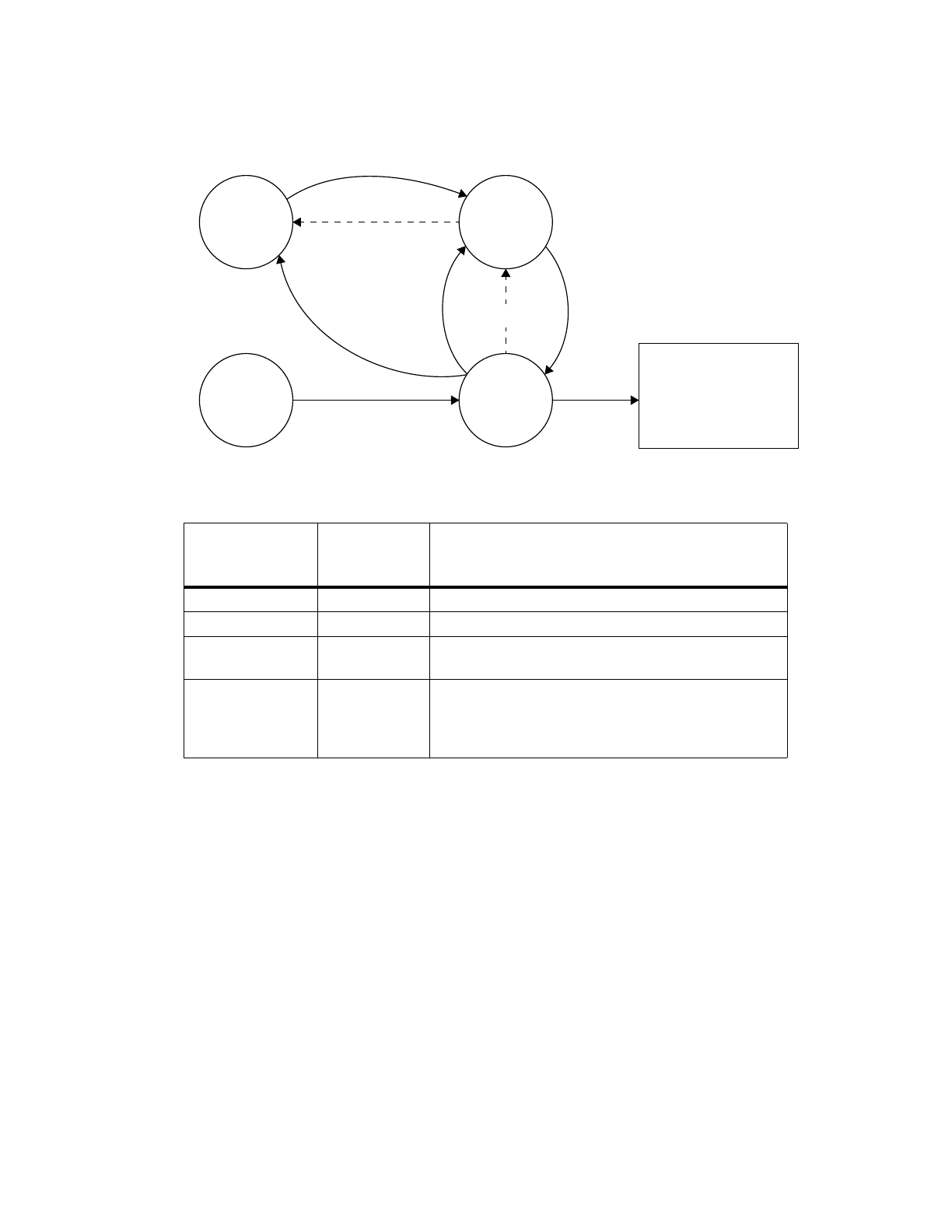
Figure 6-5 describes the watchdog state machine. In the figure, numbers in parentheses refer to
descriptions of operating modes that follow the table.
The controls described in Figure 6-5 imply three different ways of using the watchdog timer. The
modes assume that TCR[WRC] was set to allow processor reset by the watchdog timer:
1. Always take a pending watchdog interrupt, and never attempt to prevent its occurrence. (This mode
is described in the preceding text.)
a. Clear TSR[WIS] in the watchdog timer handler.
b. Never use TSR[ENW].
2. Always take a pending watchdog interrupt, but avoid it whenever possible by delaying a reset until a
second watchdog timer occurs.
This assumes that a recurring code loop of known maximum duration exists outside the interrupt
handlers, or that a FIT interrupt handler is operational. One of these mechanisms clears
TSR[ENW] more frequently than the watchdog period.
a. Clear TSR[ENW] to 0 in loop or in FIT interrupt handler.
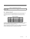
Figure 6-5. Watchdog Timer State Machine
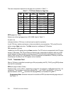
Enable Next
Watchdog
TSR[ENW]
Watchdog
Timer Status
TSR[WIS] Action When Timer Interval Expires
0 0 Set TSR[ENW] = 1.
0 1 Set TSR[ENW] = 1.
1 0 Set TSR[WIS] = 1.
If TCR[WIE] = 1 and MSR[CE] = 1, then interrupt.
1 1 Cause the watchdog reset action specified by
TCR[WRC].
On reset, copy current TCR[WRC] to TSR[WRS] and
clear TCR[WRC], disabling the watchdog timer.
WIS=0
Time-out, no interrupt
Watchdog timeout occurred, watchdog
Time-out, no interrupt Time-out
(2) SW Loop
(3) SW Loop
(1) Interrupt
Handler
(2) Interrupt
Handler
interrupt will occur if enabled
Value of TCR[WRC]
00 No reset will occur
01 Core reset
10 Chip reset
11 System reset
ENW=0
WIS=0
ENW = 1
WIS = 1
ENW=0
WIS=1
ENW = 1