


6-6 PPC405 Core User’s Manual
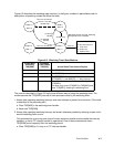
6.3 Watchdog Timer
The watchdog timer aids system recovery from software or hardware faults.
A watchdog timeout occurs on 0→1 transitions of a selected bit from the time base, as shown in the
following table.
If a watchdog timeout occurs while TSR[WIS] = 0 and TSR[ENW] = 1, a watchdog interrupt occurs if
the interrupt is enabled by TCR[WIE] and MSR[CE]. “Watchdog Timer” on page 6-6 describes
register behavior during a watchdog interrupt.
The interrupt handler should reset the TSR[WIS] bit. This is done by using mtspr to write a word to
the TSR having a 1 in TSR[WIS] and any other bits to be cleared, and a 0 in all other bits. The data
written to the TSR is not direct data, but a mask. A 1 clears a bit and a 0 has no effect.
If a watchdog timeout occurs while TSR[WIS] = 1 and TSR[ENW] = 1, a hardware reset occurs if
enabled by a non-zero value of TCR[WRC]. In other words, a reset can occur if a watchdog timeout
occurs while a previous watchdog timeout is pending. The assumption is that TSR[WIS] was not
cleared because the processor could not execute the watchdog handler, leaving reset as the only way
to restart the system. Note that after TCR[WRC] is set to a non-zero value, it cannot be reset by
software. This prevents errant software from disabling the watchdog timer reset capability. After a
reset, the initial value of TCR[WRC] = 00.
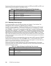
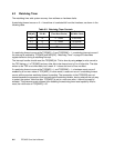
Table 6-3. Watchdog Timer Controls
TCR[WP] TBL Bit
Period
(Time Base Clocks)
Period
(200 MHz Clock)
0,0 15 2
17
clocks 0.655 msec
0,1 11 2
21
clocks 10.49 msec
1,0 7 2
25
clocks 0.168 sec
1,1 3 2
29
clocks 2.684 sec