


8-14 PPC405 Core User’s Manual
The address for a DAC is the effective address (EA) of a storage reference instruction. EAs are
always generated within a single aligned word of memory. Unaligned load and store, strings, and
multiples generate multiple EAs to be used in DAC comparisons.
Data address compare (DAC) debug events can be set to react to any byte in a larger block of
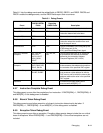
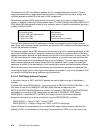
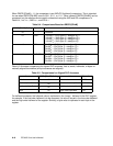
memory, in addition to reacting to a byte address match. The DAC Compare Size fields (DBCR1[D1S,
D2S]) allow DAC debug events to react to byte, halfword, word, or 8-word line address by ignoring a
number of LSBs in the EA.
The user must determine how the addresses of interest are accessed, relative to byte, halfword,
word, string, and unaligned storage instructions, and adjust the DAC compare size field appropriately
to cover the addresses of interest.
For example, suppose that a DAC debug event should react to byte 3 of a word-aligned target. A DAC
set for exact compare would not recognize a reference to that byte by load/store word or load/store
halfword instructions, because the byte address is not the EA of such instructions. In such a case, the
D1S field must be set for a wider capture range (for example, to ignore the two least significant bits
(LSBs) if word operations to the misaligned byte are to be detected). The wider capture range may
result in excess debug events (events that are within the specified capture range, but reflect byte
operations in addition to the desired byte). Such excess debug events must be handled by software.
While load/store string instructions are inherently byte addressed the processor will generate EAs
containing the largest portion of an aligned word address as possible. It may not be possible to DAC
on a specific individual byte using load/store string instructions.
8.5.13.2 DAC Range Address Compare
In this mode, the pair of DAC1 and DAC2 registers are used to define a range of addresses to
compare.
To enable DAC range, DBCR1[DA12] = 1 and one or more of DBCR1[D1R,D2R,D1W,D2W] =1. The
DAC event is seen on the DBSR[DR1,DR2,DW1,DW2] field that corresponds to the
DBCR1[D1R,D2R,D1W,D2W] field that is enabled. For example, if DBCR1[D1R] and DBCR1[D2R]
are enabled, the results of a DAC debug event are reported on DBSR[DR1, DR2]. Setting
DBCR1[DA12] =1 prohibits DAC1 and DAC2 from being used for exact address compares.
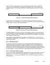
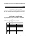
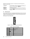
Ranges are defined to be inclusive or exclusive, using the DBCR1[DA12X], as follows:
DBCR1[DA12] = 1: Range = DAC1 ≤ range < DAC2.
DBCR1[DA12X] = 1: Range = Range low < DAC1 or DAC2 ≤ Range high.
Figure 8-9 shows the range selected in an inclusive DAC range address compare. Note that the
address in DAC1 is considered part of the range, but the address in DAC2 is not, as shown in the
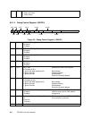
DAC 1 Size
00 Compare all bits
01 Ignore LSB (least significant bit)
10 Ignore two LSBs
11 Ignore five LSBs
Byte address
Halfword address
Word address
Cache line (
8-word) address