


9-2 PPC405 Core User’s Manual
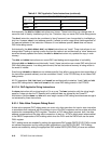
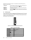
9.2 Instruction Formats
For more detailed information about instruction formats, including a summary of instruction field
usage and instruction format diagrams for the PPC405 core, see “Instruction Formats” on page 9-2.
Instructions are four bytes long. Instruction addresses are always word-aligned.
Instruction bits 0 through 5 always contain the primary opcode. Many instructions have an extended
opcode in another field. The remaining instruction bits contain additional fields. All instruction fields
belong to one of the following categories:
• Defined
These instructions contain values, such as opcodes, that cannot be altered. The instruction format
diagrams specify the values of defined fields.
• Variable
These fields contain operands, such as general purpose register selectors and immediate values,
that may vary from execution to execution. The instruction format diagrams specify the operands in
variable fields.
• Reserved
Bits in a reserved field should be set to 0. In the instruction format diagrams, reserved fields are
shaded.
If any bit in a defined field does not contain the expected value, the instruction is illegal and an illegal
instruction exception occurs. If any bit in a reserved field does not contain 0, the instruction form is
invalid and its result is architecturally undefined. Unless otherwise noted, the execute all invalid
instruction forms without causing an illegal instruction exception.
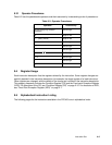
9.3 Pseudocode
The pseudocode that appears in the instruction descriptions provides a semi-formal language for
describing instruction operations.
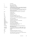
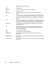
The pseudocode uses the following notation:
= Assignment
∧ AND logical operator
¬ NOT logical operator
∨ OR logical operator
⊕ Exclusive-OR (XOR) logical operator
+ Twos complement addition
– Twos complement subtraction, unary minus
× Multiplication
÷ Division yielding a quotient
% Remainder of an integer division; (33 % 32) = 1.