


5-16 PPC405 Core User’s Manual
5.8 Data Storage Interrupt
The data storage interrupt occurs when the desired access to the effective address is not permitted
for any of the following reasons:
• A U0 fault: any store to an EA with the U0 storage attribute set and CCR0[U0XE] = 1
• In the problem state with data translation enabled:
–A
zone fault
, which is any user-mode storage access (data load, store, icbi, dcbz, dcbst, or
dcbf) with an effective address with (ZPR field) = 00. (dcbt and dcbtst will no-op in this
situation, rather than cause an interrupt. The instructions dcbi, dccci, icbt, and iccci, being
privileged, cannot cause zone fault data storage interrupts.)
– Data store or dcbz to an effective address with the WR bit clear and (ZPR field) ≠ 11. (The
privileged instructions dcbi and dccci are treated as “stores,” but will cause privileged program
interrupts, rather than data storage interrupts.)
• In the supervisor state with data translation enabled:
– Data store, dcbi, dcbz, or dccci to an effective address with the WR bit clear and (ZPR field)
other than 11 or 10.
Programming Note: The icbi, icbt, and iccci instructions are treated as loads from the
addressed byte with respect to address translation and protection. Instruction cache operations
use MSR[DR], not MSR[IR], to determine translation of their operands. Instruction storage
interrupts and Instruction-side TLB Miss Interrupts are associated with the
fetching
of instructions,
not with the execution of instructions. Data storage interrupts and data TLB miss interrupts are
associated with the
execution
of instruction cache operations.
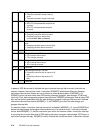
When a data storage interrupt is detected, the PPC405 suppresses the instruction causing the
interrupt and writes the instruction address in SRR0. The Data Exception Address Register (DEAR) is
loaded with the data address that caused the access violation. ESR bits are loaded as shown in
Table 5-7 on page 5-17 to provide further information about the error. The current contents of the
MSR are loaded into SRR1, and MSR bits are then loaded with the values shown in Table 5-7.
The high-order 16 bits of the program counter are then loaded with the contents of the EVPR and the
low-order 16 bits of the program counter are loaded with 0x0300. Interrupt processing begins at the
new address in the program counter. Executing the return from interrupt instruction (rfi) restores the
contents of the program counter and the MSR from SRR0 and SRR1, respectively, and the PPC405
resumes execution at the new program counter address.