


Fixed-Point Interrupts and Exceptions 5-23
simultaneously, the contents of the MSR are written into SRR1 and the MSR is written with the values
shown in Table 5-17. The high-order 16 bits of the program counter are then written with the contents
of the EVPR and the low-order 16 bits of the program counter are written with 0x1000. Interrupt
processing begins at the address in the program counter.
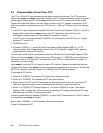
To clear a PIT interrupt, the interrupt handling routine must clear the PIT interrupt bit, TSR[PIS].
Clearing is performed by writing a word to TSR, using an mtspr instruction, that has 1 in bit positions
to be cleared and 0 in all other bit positions. The data written to the TSR is not direct data, but a mask;
a 1 clears the bit and 0 has no effect.
Executing an rfi instruction restores the program counter from SRR0 and the MSR from SRR1, and
execution resumes at the address in the program counter.
5.17 Fixed Interval Timer (FIT) Interrupt
For a discussion of the PPC405 timer facilities, see Chapter 6, “Timer Facilities.” The FIT is described
in “Fixed Interval Timer (FIT) Interrupt” on page 5-23.
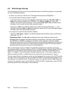
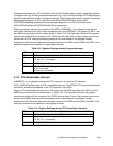
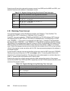
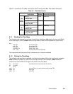
If the FIT interrupt is enabled by TCR[FIE] and MSR[EE], the PPC405 initiates a FIT interrupt after
detecting a time-out from the FIT. Time-out is detected when, at the beginning of a clock cycle,
TSR[FIS] = 1. (This occurs on the second cycle after the 0 → 1 transition of the appropriate time-base
bit.) The PPC405 immediately takes the interrupt. The address of the next sequential instruction is
written into SRR0; simultaneously, the contents of the MSR are written into SRR1 and the MSR is
written with the values shown in Table 5-18. The high-order 16 bits of the program counter are then
written with the contents of the EVPR and the low-order 16 bits of the program counter are written
with 0x1010. Interrupt processing begins at the address in the program counter.
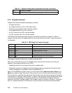
To clear a FIT interrupt, the interrupt handling routine must clear the FIT interrupt bit, TSR[FIS].
Clearing is performed by writing a word to TSR, using an mtspr instruction, that has 1 in any bit
positions to be cleared and 0 in all other bit positions. The data written to the TSR is not direct data,
but a mask; a 1 clears a bit and 0 has no effect.
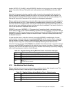
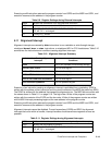
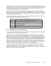
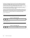
Table 5-17. Register Settings during Programmable Interval Timer Interrupts
SRR0 Written with the address of the next instruction to be executed
SRR1 Written with the contents of the MSR
MSR AP, APE, WE, EE, PR, FP, FE0, DWE, FE1, IR, DR ← 0
CE, ME, DE ← unchanged
PC EVPR[0:15] || 0x1000
TSR PIS ← 1