


Fixed-Point Interrupts and Exceptions 5-9
5.5.2 Save/Restore Registers 0 and 1 (SRR0–SRR1)
SRR0 and SRR1 are 32-bit registers that hold the interrupted machine context when a noncritical
interrupt is processed. On interrupt, SRR0 is set to the current or next instruction address and the
contents of the MSR are written to SRR1. When an rfi instruction is executed at the end of the
interrupt handler, the program counter and the MSR are restored from SRR0 and SRR1, respectively.
The contents of SRR0 and SRR1 can be written into GPRs using the mfspr instruction. The contents
of GPRs can be written to SRR0 and SRR1 using the mtspr instruction.
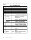
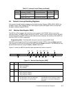
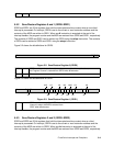
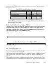
Figure 5-2 shows the bit definitions for SRR0.
.
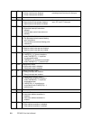
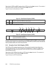
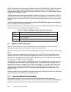
Figure 5-3 shows the bit definitions for SRR1.
5.5.3 Save/Restore Registers 2 and 3 (SRR2–SRR3)
SRR2 and SRR3 are 32-bit registers that hold the interrupted machine context when a critical
interrupt is processed. On interrupt, SRR2 is set to the current or next instruction address and the
contents of the MSR are written to SRR3. When an rfci instruction is executed at the end of the
interrupt handler, the program counter and the MSR are restored from SRR2 and SRR3, respectively.
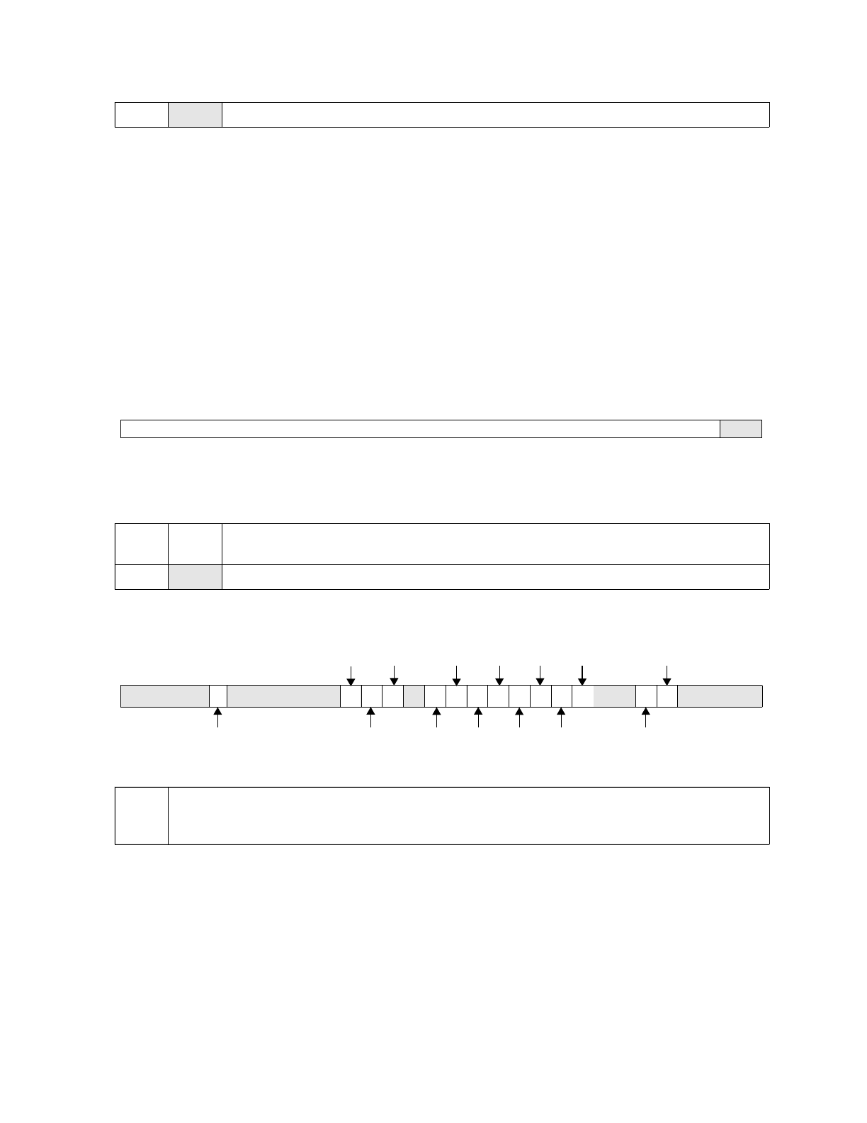
28:31 Reserved
Figure 5-2. Save/Restore Register 0 (SRR0)
0:29 SRR0 receives an instruction address when a non-critical interrupt is taken;
the Program Counter is restored from SRR0 when rfi executes.
30:31
Reserved
Figure 5-3. Save/Restore Register 1 (SRR1)
0:31 SRR1 receives a copy of the MSR when an
interrupt is taken; the MSR is restored from
SRR1 when rfi executes.
0 29 30 31
0 567 11 12 13 14 15 16 17 18 19 20 21 22 23 24 25 26 27 28 31
DE
CE
EE
IR
WE
PR
DRME
FP
FE0
FE1
DWE
AP
APE