


5-22 PPC405 Core User’s Manual
5.14 System Call Interrupt
System call interrupts occur when a sc instruction is executed. The PPC405 writes the address of the
instruction following the sc into SRR0. The contents of the MSR are written into SRR1 and the MSR
bits are written with the values shown in Table 5-15. The high-order 16 bits of the program counter are
then written with the contents of the EVPR and the low-order 16 bits of the program counter are
written with 0x0C00. Interrupt processing begins at the new address in the program counter.
Executing an rfi instruction restores the program counter from SRR0 and the MSR from SRR1, and
execution resumes at the address in the program counter.
5.15 APU Unavailable Interrupt
If MSR[AP] = 0, an attempt to execute an APU instruction for which an APU asserts
APU_C405DcdApuOp causes an APU unavailable interrupt. The PPC405 does not execute the
instruction, but writes the address of the APU instruction into SRR0.
After an APU unavailable interrupt, the contents of the MSR are written into SRR1 and the MSR bits
are written with the values shown in Table 5-16. The high-order 16 bits of the program counter are
written with the contents of the EVPR; the low-order 16 bits of the program counter are written with
0x0F20. Interrupt processing begins at the new address in the program counter.
Executing an rfi instruction restores the program counter from SRR0 and the MSR from SRR1, and
execution resumes at the address in the program counter.
5.16 Programmable Interval Timer (PIT) Interrupt
For a discussion of the PPC405 timer facilities, see Chapter 6, “Timer Facilities.” The PIT is described
in “Programmable Interval Timer (PIT)” on page 6-4.
If the PIT interrupt is enabled by TCR[PIE] and MSR[EE], the PPC405 initiates a PIT interrupt after
detecting a time-out from the PIT. Time-out is detected when, at the beginning of a clock cycle,
TSR[PIS] = 1. (This occurs on the cycle after the PIT decrements on a PIT count of 1.) The PPC405
immediately takes the interrupt. The address of the next sequential instruction is saved in SRR0;
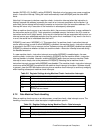
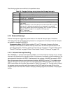
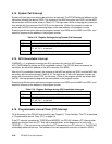
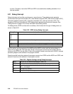
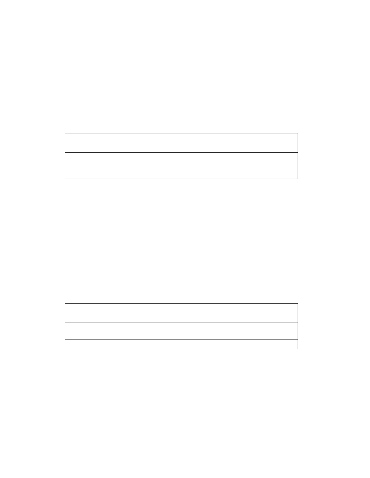
Table 5-15. Register Settings during System Call Interrupts
SRR0 Written with the address of the instruction following the sc instruction
SRR1 Written with the contents of the MSR
MSR AP, APE, WE, EE, PR, FP, FE0, DWE, FE1, IR, DR ← 0
CE, ME, DE ← unchanged
PC EVPR[0:15] || 0x0C00
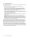
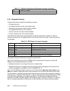
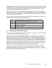
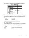
Table 5-16. Register Settings during APU Unavailable Interrupts
SRR0 Written with the address of the excepting instruction
SRR1 Written with the contents of the MSR
MSR AP, APE, WE, EE, PR, FP, FE0, DWE, FE1, IR, DR ← 0
CE, ME, DE ← unchanged
PC EVPR[0:15] || 0x0F20