


5-14 PPC405 Core User’s Manual
SRR2. Simultaneously, the contents of the MSR are saved in SRR3. MSR[CE] is reset to 0 to prevent
another critical interrupt or the watchdog timer first time-out interrupt from interrupting the critical
interrupt handler before SRR2 and SRR3 get saved. MSR[DE] is reset to 0 to disable debug interrupts
during the critical interrupt handler.
The MSR is also written with the values shown in Table 5-4 on page 5-14. The high-order 16 bits of
the program counter are then loaded with the contents of the EVPR and the low-order 16 bits of the
program counter are loaded with 0x0100. Interrupt processing begins at the address in the program
counter.
Inside the interrupt handling routine, after the contents of SRR2/SRR3 are saved, critical interrupts
can be enabled again by setting MSR[CE] = 1.
Executing an rfci instruction restores the program counter from SRR2 and the MSR from SRR3, and
execution resumes at the address in the program counter.
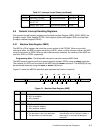
5.7 Machine Check Interrupts
When an external bus error occurs on an instruction fetch, and execution of that instruction is
subsequently attempted, a machine check—instruction interrupt occurs.
When an external bus error occurs while attempting data accesses, a machine check—data interrupt
occurs.
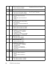
When an instruction-side machine check interrupt occurs, the PPC405 stores the address of the
excepting instruction in SRR2. When a data-side machine check occurs, the PPC405 stores the
address of the next sequential instruction in SRR2. Simultaneously, for all machine check interrupts,
the contents of the MSR are loaded into SRR3.
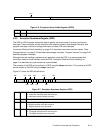
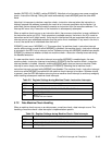
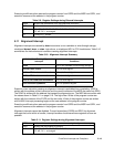
The MSR Machine Check Enable bit (MSR[ME]) is reset to 0 to disable another machine check from
interrupting the machine check interrupt handling routine. The other MSR bits are loaded with the
values shown in Table 5-5 on page 5-15 and Table 5-6 on page 5-15. The high-order 16 bits of the
program counter are then written with the contents of the EVPR and the low-order 16 bits of the
program counter are written with 0x0200. Interrupt processing begins at the new address in the
program counter.
Executing an rfci instruction restores the program counter from SRR2 and the MSR from SRR3, and
execution resumes at the address in the program counter.
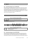
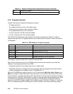
5.7.1 Instruction Machine Check Handling
When a machine check occurs on an instruction fetch,
and execution of that instruction is
subsequently attempted
, a machine check—instruction interrupt occurs. If enabled by MSR[ME], the
processor reports the machine check—instruction interrupt by vectoring to the machine check
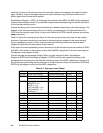
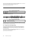
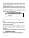
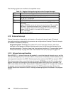
Table 5-4. Register Settings during Critical Input Interrupts
SRR2 Written with the address of the next instruction to be executed
SRR3 Written with the contents of the MSR
MSR AP, APE, WE, CE, EE, PR, FP, FE0, DWE, DE, FE1, IR, DR←0
ME← unchanged
PC EVPR[0:15] || 0x0100