


2-2 PPC405 Core User’s Manual
2.2.1 Storage Attributes
The PowerPC Architecture defines storage attributes that control data and instruction accesses.
Storage attributes are provided to control cache write-through policy (the W storage attribute),
cachability (the I storage attribute), memory coherency in multiprocessor environments (the M
storage attribute), and guarding against speculative memory accesses (the G storage attribute). The
IBM PowerPC Embedded Environment defines additional storage attributes for storage compression
(the U0 storage attribute) and byte ordering (the E storage attribute).
The PPC405 core provides two control mechanisms for the W, I, U0, G, and E attributes. Because the
PPC405 core does not provide hardware support for multiprocessor environments, the M storage
attribute, when present, has no effect.
When the PPC405 core operates in virtual mode (address translation is enabled), each storage
attribute is controlled by the W, I, U0, G, and E fields in the translation lookaside buffer (TLB) entry for
each memory page. The size of memory pages, and hence the size of storage attribute control
regions, is variable. Multiple sizes can be in effect simultaneously on different pages.
When the PPC405 core operates in real mode (address translation is disabled), storage attribute
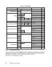
control registers control the corresponding storage attributes. These registers are:
• Data Cache Write-through Register (DCWR)
• Data Cache Cachability Register (DCCR)
• Instruction Cache Cachability Register (ICCR)
• Storage Guarded Register (SGR)
• Storage Little-Endian Register (SLER)
• Storage User-defined 0 Register (SU0R)
Each storage attribute control register contains 32 bits; each bit controls one of thirty-two 128MB
storage attribute control regions. Bit 0 of each register controls the lowest-order region, with
ascending bits controlling ascending regions in memory. The storage attributes in each storage
attribute region are set independently of each other and of the storage attributes for other regions.
2.3 Registers
All PPC405 registers are listed in this section. Some of the frequently-used registers are described in
detail. Other registers are covered in their respective topic chapters (for example, the cache registers
are described in Chapter 4, “Cache Operations”). All registers are summarized in Chapter 10,
“Register Summary.”
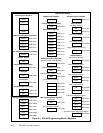
The registers are grouped into categories: General Purpose Registers (GPRs), Special Purpose
Registers (SPRs), Time Base Registers (TBRs), the Machine State Register (MSR), the Condition
Register (CR), and, in standard products, Device Control Registers (DCRs). Different instructions are
used to access each category of registers.
For all registers with fields marked as
reserved
, the reserved fields should be written as 0 and read as
undefined
. That is, when writing to a register with a reserved field, write a 0 to the reserved field.
When reading from a register with a reserved field, ignore that field.