4-16 Vol. 3
PAGING
ters. (This is different from the other paging modes, in which there is one hierarchy
referenced by CR3.)
Section 4.4.1 discusses the PDPTE registers. Section 4.4.2 describes linear-address
translation with PAE paging.
4.4.1 PDPTE Registers
When PAE paging is used, CR3 references the base of a 32-Byte page-directory-
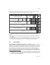
pointer table. Table 4-7 illustrates how CR3 is used with PAE paging.
The page-directory-pointer-table comprises four (4) 64-bit entries called PDPTEs.
Each PDPTE controls access to a 1-GByte region of the linear-address space. Corre-
sponding to the PDPTEs, the logical processor maintains a set of four (4) internal,
non-architectural PDPTE registers, called PDPTE0, PDPTE1, PDPTE2, and PDPTE3.
The logical processor loads these registers from the PDPTEs in memory as part of
certain executions the MOV to CR instruction:
• If an execution MOV to CR0 or MOV to CR4 causes the logical processor to
transition from either no paging or 32-bit paging to PAE paging (see Section
4.1.2), the PDPTEs are loaded from the address in CR3.
• If MOV to CR3 is executed while the logical processor is using PAE paging, the
PDPTEs are loaded from the address being loaded into CR3.
• If PAE paging is in use and a task switch changes the value of CR3, the PDPTEs
are loaded from the address in the new CR3 value.
• Certain VMX transitions load the PDPTE registers. See Section 4.11.1.
Unless the caches are disabled, the processor uses the WB memory type to load the
PDPTEs from memory.
1
Table 4-7. Use of CR3 with PAE Paging
Bit
Position(s)
Contents
4:0 Ignored
31:5 Physical address of the 32-Byte aligned page-directory-pointer table used for
linear-address translation
63:32 Ignored (these bits exist only on processors supporting the Intel-64 architecture)
1. Older IA-32 processors used the UC memory type when loading the PDPTEs. This behavior is
model-specific and not architectural.


