15-14 Vol. 3
MACHINE-CHECK ARCHITECTURE
When IA32_MCG_CAP[10] = 1, the IA32_MCi_CTL2 MSR for each bank
exists, i.e. reads and writes to these MSR are supported. However, signaling
interface for corrected MC errors may not be supported in all banks.
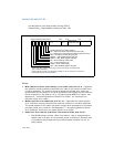
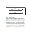
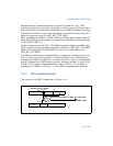
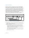
The layout of IA32_MCi_CTL2 is shown in Figure 15-8:
• Corrected error count threshold, bits 14:0 — Software must initialize this
field. The value is compared with the corrected error count field in
IA32_MCi_STATUS, bits 38 through 52. An overflow event is signaled to the CMCI
LVT entry (see
Table 10-1) in the APIC when the count value equals the threshold
value. The new LVT entry in the APIC is at 02F0H offset from the APIC_BASE. If
CMCI interface is not supported for a particular bank (but IA32_MCG_CAP[10]
= 1)
, this field will always read 0.
• CMCI_EN-Corrected error interrupt enable/disable/indicator, bits 30 —
Software sets this bit to enable the generation of corrected machine-check error
interrupt (CMCI). If CMCI interface is not supported for a particular bank (but
IA32_MCG_CAP[10] = 1), this bit is writeable but will always return 0 for that
bank. This bit also indicates CMCI is supported or not supported in the corre-
sponding bank. See Section 15.5 for details of software detection of CMCI facility.
Some microarchitectural sub-systems that are the source of corrected MC
errors may be shared by more than one logical processors. Consequently,
the facilities for reporting MC errors and controlling mechanisms may be
shared by more than one logical processors. For example, the
IA32_MCi_CTL2 MSR is shared between logical processors sharing a
processor core. Software is responsible to program IA32_MCi_CTL2 MSR in
a consistent manner with CMCI delivery and usage.
After processor reset, IA32_MCi_CTL2 MSRs are zero’ed.
Figure 15-8. IA32_MCi_CTL2 Register
CMCI_EN—Enable/disable CMCI
63
15
Reserved
29
Corrected error count threshold
0
14
3130
Reserved


