Vol. 3 10-25
ADVANCED PROGRAMMABLE INTERRUPT CONTROLLER (APIC)
• xAPIC mode: IA32_APIC_BASE[EN]=1 and IA32_APIC_BASE[EXTD]=0
• x2APIC mode: IA32_APIC_BASE[EN]=1 and IA32_APIC_BASE[EXTD]=1
• Invalid: IA32_APIC_BASE[EN]=0 and IA32_APIC_BASE[EXTD]=1
The state corresponding to EXTD=1 and EN=0 is not valid and it is not possible to get
into this state. Values written to the IA32_APIC_BASE_MSR that attempt a transition
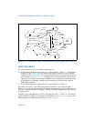
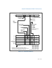
from a valid state to this invalid state will cause a GP fault. Figure 10-11 shows the
comprehensive state transition diagram for a local x2APIC unit.
On coming out of RESET, the local APIC unit is enabled and is in the xAPIC mode:
IA32_APIC_BASE[EN]=1 and IA32_APIC_BASE[EXTD]=0. The APIC registers are
initialized as:
• The local APIC ID is initialized by hardware with a 32 bit ID (x2APIC ID). The
lowest 8 bits of the x2APIC ID is the legacy local xAPIC ID, and is stored in the
upper 8 bits of the APIC register for access in xAPIC mode.
• The following APIC registers are reset to all zeros for those fields that are defined
in the xAPIC mode:
— IRR, ISR, TMR, ICR, LDR, TPR, Divide Configuration Register (See Chapter 8
of “Intel® 64 and IA-32 Architectures Software Developer’s Manual“, Vol. 3B
for details of individual APIC registers),
— Timer initial count and timer current count registers,
• The LVT registers are reset to 0s except for the mask bits; these are set to 1s.
• The local APIC version register is not affected.
• The Spurious Interrupt Vector Register is initialized to 000000FFH.
• The DFR (available only in xAPIC mode) is reset to all 1s.
• SELF IPI register is reset to zero.


