16-8 Vol. 3
DEBUGGING, PROFILING BRANCHES AND TIME-STAMP COUNTER
16.2.6 Debug Registers and Intel
®
64 Processors
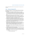
For Intel 64 architecture processors, debug registers DR0–DR7 are 64 bits. In 16-bit
or 32-bit modes (protected mode and compatibility mode), writes to a debug register
fill the upper 32 bits with zeros. Reads from a debug register return the lower 32 bits.
In 64-bit mode, MOV DRn instructions read or write all 64 bits. Operand-size prefixes
are ignored.
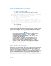
In 64-bit mode, the upper 32 bits of DR6 and DR7 are reserved and must be written
with zeros. Writing 1 to any of the upper 32 bits results in a #GP(0) exception (see
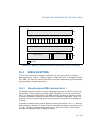
Figure 16-2). All 64 bits of DR0–DR3 are writable by software. However, MOV DRn
instructions do not check that addresses written to DR0–DR3 are in the linear-
address limits of the processor implementation (address matching is supported only
on valid addresses generated by the processor implementation). Break point condi-
tions for 8-byte memory read/writes are supported in all modes.
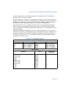
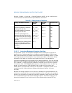
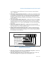
Data operations that do not trap
- Read or write
- Read
- Read or write
- Read or write
- Read
- Read or write
A0000H
A0002H
A0003H
B0000H
C0000H
C0004H
1
1
4
2
2
4
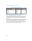
Table 16-1. Breakpoint Examples (Contd.)
Debug Register Setup
Debug Register R/Wn Breakpoint Address LENn


