Vol. 3 10-23
ADVANCED PROGRAMMABLE INTERRUPT CONTROLLER (APIC)
field, VM-exit MSR-load address filed, and VM-entry MSR-load address field in Intel®
64 and IA-32 Architectures Software Developer’s Manual, Volume 3B).
The X2APIC MSRs cannot to be loaded and stored on VMX transitions. A VMX transi-
tion fails if the VMM has specified that the transition should access any MSRs in the
address range from 0000_0800H to 0000_08FFH (the range used for accessing the
X2APIC registers). Specifically, processing of an 128-bit entry in any of the VMX-
transition MSR areas fails if bits 31:0 of that entry (represented as ENTRY_LOW_DW)
satisfies the expression: “ENTRY_LOW_DW & FFFFF800H = 00000800H”. Such a
failure causes an associated VM entry to fail (by reloading host state) and causes an
associated VM exit to lead to VMX abort.
10.5.5 Directed EOI with x2APIC Mode
Directed EOI capability is intended to enable system software to perform directed
EOIs to specific IOxAPICs in the system. System software desiring to perform a
directed EOI would do the following:
• inhibit the broadcast of EOI message by setting bit 12 of the Spurious Interrupt
Vector Register, and
• following the EOI to the local x2APIC unit for a level triggered interrupt, perform
a directed EOI to the IOxAPIC generating the interrupt by writing to its EOI
register.
Supporting directed EOI capability would require system software to retain a
mapping associating level triggered interrupts with IOxAPICs in the system.
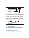
Bit 12 of the Spurious Interrupt Vector Register (SVR) in the local x2APIC unit
controls the generation of the EOI broadcast if the Directed EOI capability is
supported. This bit is reserved to 0 if the processor doesn't support Directed EOI. If
SVR[bit 12] is set, a broadcast EOI is not generated on an EOI cycle even if the asso
-
ciated TMR bit is indicating the current interrupt is a level triggered interrupt. Layout
of the Spurious Interrupt Vector Register is shown in
Figure 10-9.


