15-20 Vol. 3
MACHINE-CHECK ARCHITECTURE
CMCI interrupt delivery is configured by writing to the LVT CMCI register
entry in the local APIC register space at default address of APIC_BASE +
2F0H. A CMCI interrupt can be delivered to more than one logical processors
if multiple logical processors are affected by the associated MC errors. For
example, if a corrected bit error in a cache shared by two logical processors
caused a CMCI, the interrupt will be delivered to both logical processors
sharing that microarchitectural sub-system. Similarly, package level errors
may cause CMCI to be delivered to all logical processors within the package.
However, system level errors will not be handled by CMCI.
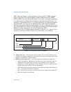
The format of the LVT CMCI register is shown in Figure 15-10. The LVT entry
allows the 4 delivery modes, an 8 bit interrupt vector, and masking.
• Vector, bits 7:0 — The interrupt vector number. The local APIC allows values
16-255 in this register. Values of 0 through 15 will result in an illegal vector to be
logged in the APIC error status register.
• Delivery mode, bits 10:8 — The following delivery modes are supported:
— 000B: Fixed delivery. Delivers an interrupt to the vector specified in bits 7:0.
— 010B: SMI Delivers an SMI interrupt to the processor core through the
processor's local SMI signal path. When using this delivery mode, the vector
field should be set to 00H for future compatibility.
— 100B: NMI Delivers an NMI interrupt to the logical processor affected by the
error. The vector information is ignored.
— Entry 101B (INIT) and entry 111B (ExtINT) are not supported by CMCI LVT.
— Other bit patterns are reserved.
Figure 15-10. Local APIC CMCI LVT Register
MASK
31
11
Reserved
15
Delivery Status
010
1716
Reserved
78
12
13
Delivery Mode
Vector Number
APIC_BASE + 2F0H


