16-4 Vol. 3
DEBUGGING, PROFILING BRANCHES AND TIME-STAMP COUNTER
16.2.1 Debug Address Registers (DR0-DR3)
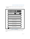
Each of the debug-address registers (DR0 through DR3) holds the 32-bit linear
address of a breakpoint (see Figure 16-1). Breakpoint comparisons are made before
physical address translation occurs. The contents of debug register DR7 further spec-
ifies breakpoint conditions.
16.2.2 Debug Registers DR4 and DR5
Debug registers DR4 and DR5 are reserved when debug extensions are enabled
(when the DE flag in control register CR4 is set) and attempts to reference the DR4
and DR5 registers cause invalid-opcode exceptions (#UD). When debug extensions
are not enabled (when the DE flag is clear), these registers are aliased to debug
registers DR6 and DR7.
16.2.3 Debug Status Register (DR6)
The debug status register (DR6) reports debug conditions that were sampled at the
time the last debug exception was generated (see Figure 16-1). Updates to this
register only occur when an exception is generated. The flags in this register show
the following information:
• B0 through B3 (breakpoint condition detected) flags (bits 0 through 3)
— Indicates (when set) that its associated breakpoint condition was met when a
debug exception was generated. These flags are set if the condition described for
each breakpoint by the LENn, and R/Wn flags in debug control register DR7 is
true. They may or may not be set if the breakpoint is not enabled by the Ln or the
Gn flags in register DR7. Therefore on a #DB, a debug handler should check only
those B0-B3 bits which correspond to an enabled breakpoint.
• BD (debug register access detected) flag (bit 13) — Indicates that the next
instruction in the instruction stream accesses one of the debug registers (DR0
through DR7). This flag is enabled when the GD (general detect) flag in debug
control register DR7 is set. See Section 16.2.4, “Debug Control Register (DR7),”
for further explanation of the purpose of this flag.
• BS (single step) flag (bit 14) — Indicates (when set) that the debug exception
was triggered by the single-step execution mode (enabled with the TF flag in the
EFLAGS register). The single-step mode is the highest-priority debug exception.
When the BS flag is set, any of the other debug status bits also may be set.
• BT (task switch) flag (bit 15) — Indicates (when set) that the debug
exception resulted from a task switch where the T flag (debug trap flag) in the
TSS of the target task was set. See Section 7.2.1, “Task-State Segment (TSS),”
for the format of a TSS. There is no flag in debug control register DR7 to enable
or disable this exception; the T flag of the TSS is the only enabling flag.
Certain debug exceptions may clear bits 0-3. The remaining contents of the DR6
register are never cleared by the processor. To avoid confusion in identifying debug


