Vol. 3 17-3
8086 EMULATION
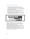
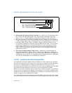
• A single interrupt table, called the “interrupt vector table” or “interrupt table,” is
provided for handling interrupts and exceptions (see Figure 17-2). The interrupt
table (which has 4-byte entries) takes the place of the interrupt descriptor table
(IDT, with 8-byte entries) used when handling protected-mode interrupts and
exceptions. Interrupt and exception vector numbers provide an index to entries
in the interrupt table. Each entry provides a pointer (called a “vector”) to an
interrupt- or exception-handling procedure. See
Section 17.1.4, “Interrupt and
Exception Handling”, for more details. It is possible for software to relocate the
IDT by means of the LIDT instruction on IA-32 processors beginning with the
Intel386 processor.
• The x87 FPU is active and available to execute x87 FPU instructions in real-
address mode. Programs written to run on the Intel 8087 and Intel 287 math
coprocessors can be run in real-address mode without modification.
The following extensions to the Intel 8086 execution environment are available in the
IA-32 architecture’s real-address mode. If backwards compatibility to Intel 286 and
Intel 8086 processors is required, these features should not be used in new programs
written to run in real-address mode.
• Two additional segment registers (FS and GS) are available.
• Many of the integer and system instructions that have been added to later IA-32
processors can be executed in real-address mode (see
Section 17.1.3, “Instruc-
tions Supported in Real-Address Mode”).
• The 32-bit operand prefix can be used in real-address mode programs to execute
the 32-bit forms of instructions. This prefix also allows real-address mode
programs to use the processor’s 32-bit general-purpose registers.
• The 32-bit address prefix can be used in real-address mode programs, allowing
32-bit offsets.
The following sections describe address formation, registers, available instructions,
and interrupt and exception handling in real-address mode. For information on I/O in
real-address mode, see Chapter 13, “Input/Output”, of the Intel® 64 and IA-32
Architectures Software Developer’s Manual, Volume 1.
17.1.1 Address Translation in Real-Address Mode
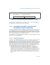
In real-address mode, the processor does not interpret segment selectors as indexes
into a descriptor table; instead, it uses them directly to form linear addresses as the
8086 processor does. It shifts the segment selector left by 4 bits to form a 20-bit
base address (see
Figure 17-1). The offset into a segment is added to the base
address to create a linear address that maps directly to the physical address space.
When using 8086-style address translation, it is possible to specify addresses larger
than 1 MByte. For example, with a segment selector value of FFFFH and an offset of
FFFFH, the linear (and physical) address would be 10FFEFH (1 megabyte plus 64
KBytes). The 8086 processor, which can form addresses only up to 20 bits long, trun
-
cates the high-order bit, thereby “wrapping” this address to FFEFH. When operating


