2-22 Vol. 3
SYSTEM ARCHITECTURE OVERVIEW
EM Emulation (bit 2 of CR0) — Indicates that the processor does not have an
internal or external x87 FPU when set; indicates an x87 FPU is present when
clear. This flag also affects the execution of
MMX/SSE/SSE2/SSE3/SSSE3/SSE4 instructions.
When the EM flag is set, execution of an x87 FPU instruction generates a
device-not-available exception (#NM). This flag must be set when the
processor does not have an internal x87 FPU or is not connected to an
external math coprocessor. Setting this flag forces all floating-point instruc
-
tions to be handled by software emulation. Table 9-2 shows the recom-
mended setting of this flag, depending on the IA-32 processor and x87 FPU
or math coprocessor present in the system.
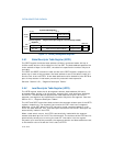
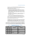
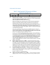
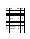
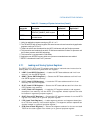
Table 2-1 shows the interaction
of the EM, MP, and TS flags.
Also, when the EM flag is set, execution of an MMX instruction causes an
invalid-opcode exception (#UD) to be generated (see Table 12-1). Thus, if an
IA-32 or Intel 64 processor incorporates MMX technology, the EM flag must
be set to 0 to enable execution of MMX instructions.
Similarly for SSE/SSE2/SSE3/SSSE3/SSE4 extensions, when the EM flag is
set, execution of most SSE/SSE2/SSE3/SSSE3/SSE4 instructions causes an
invalid opcode exception (#UD) to be generated (see
Table 13-1). If an IA-32
or Intel 64 processor incorporates the SSE/SSE2/SSE3/SSSE3/SSE4 exten-
sions, the EM flag must be set to 0 to enable execution of these extensions.
SSE/SSE2/SSE3/SSSE3/SSE4 instructions not affected by the EM flag
include: PAUSE, PREFETCHh, SFENCE, LFENCE, MFENCE, MOVNTI, CLFLUSH,
CRC32, and POPCNT.
MP Monitor Coprocessor (bit 1 of CR0). — Controls the interaction of the
WAIT (or FWAIT) instruction with the TS flag (bit 3 of CR0). If the MP flag is
set, a WAIT instruction generates a device-not-available exception (#NM) if
the TS flag is also set. If the MP flag is clear, the WAIT instruction ignores the
setting of the TS flag.
Table 9-2 shows the recommended setting of this flag,
depending on the IA-32 processor and x87 FPU or math coprocessor present
in the system.
Table 2-1 shows the interaction of the MP, EM, and TS flags.
PE Protection Enable (bit 0 of CR0) — Enables protected mode when set;
enables real-address mode when clear. This flag does not enable paging
directly. It only enables segment-level protection. To enable paging, both the
PE and PG flags must be set.
See also: Section 9.9, “Mode Switching.”
PCD Page-level Cache Disable (bit 4 of CR3) — Controls caching of the first
paging structure of the current paging-structure hierarchy. When the PCD
1 1 1 #NM Exception #NM exception.
Table 2-1. Action Taken By x87 FPU Instructions for Different
Combinations of EM, MP, and TS
CR0 Flags x87 FPU Instruction Type


