11-2 Vol. 3
MEMORY CACHE CONTROL
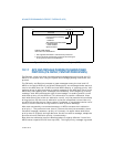
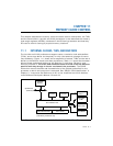
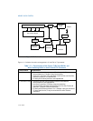
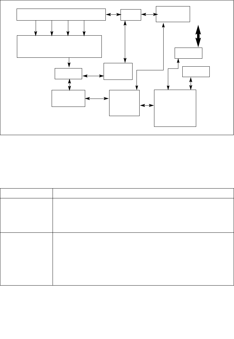
Figure 11-2 shows the cache arrangement of Intel Core i7 processor.
Figure 11-2. Cache Structure of the Intel Core i7 Processors
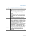
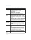
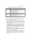
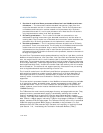
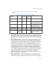
Table 11-1. Characteristics of the Caches, TLBs, Store Buffer, and
Write Combining Buffer in Intel 64 and IA-32 Processors
Cache or Buffer Characteristics
Trace Cache
1
• Pentium 4 and Intel Xeon processors (Based on Intel NetBurst
microarchitecture): 12 Kμops, 8-way set associative.
• Intel Core i7, Intel Core 2 Duo, Intel Atom, Intel Core Duo, Intel Core Solo,
Pentium M processor: not implemented.
• P6 family and Pentium processors: not implemented.
L1 Instruction Cache • Pentium 4 and Intel Xeon processors (Based on Intel NetBurst
microarchitecture): not implemented.
• Intel Core i7 processor: 32-KByte, 4-way set associative.
• Intel Core 2 Duo, Intel Atom, Intel Core Duo, Intel Core Solo, Pentium M
processor: 32-KByte, 8-way set associative.
• P6 family and Pentium processors: 8- or 16-KByte, 4-way set associative,
32-byte cache line size; 2-way set associative for earlier Pentium
processors.
Instruction Decoder and front end
Out-of-Order Engine
Chipset
Data Cache
Unit (L1)
Instruction
Cache
STLB
Data TLB
L2 Cache
ITLB
L3 Cache
IMC
QPI


