10-60 Vol. 3
ADVANCED PROGRAMMABLE INTERRUPT CONTROLLER (APIC)
The IRR contains the active interrupt requests that have been accepted, but not yet
dispatched to the processor for servicing. When the local APIC accepts an interrupt,
it sets the bit in the IRR that corresponds the vector of the accepted interrupt. When
the processor core is ready to handle the next interrupt, the local APIC clears the
highest priority IRR bit that is set and sets the corresponding ISR bit. The vector for
the highest priority bit set in the ISR is then dispatched to the processor core for
servicing.
While the processor is servicing the highest priority interrupt, the local APIC can send
additional fixed interrupts by setting bits in the IRR. When the interrupt service
routine issues a write to the EOI register (see
Section 10.9.5, “Signaling Interrupt
Servicing Completion”), the local APIC responds by clearing the highest priority ISR
bit that is set. It then repeats the process of clearing the highest priority bit in the IRR
and setting the corresponding bit in the ISR. The processor core then begins
executing the service routing for the highest priority bit set in the ISR.
If more than one interrupt is generated with the same vector number, the local APIC
can set the bit for the vector both in the IRR and the ISR. This means that for the
Pentium 4 and Intel Xeon processors, the IRR and ISR can queue two interrupts for
each interrupt vector: one in the IRR and one in the ISR. Any additional interrupts
issued for the same interrupt vector are collapsed into the single bit in the IRR.
For the P6 family and Pentium processors, the IRR and ISR registers can queue no
more than two interrupts per priority level, and will reject other interrupts that are
received within the same priority level.
If the local APIC receives an interrupt with a priority higher than that of the interrupt
currently in serviced, and interrupts are enabled in the processor core, the local APIC
dispatches the higher priority interrupt to the processor immediately (without
waiting for a write to the EOI register). The currently executing interrupt handler is
then interrupted so the higher-priority interrupt can be handled. When the handling
of the higher-priority interrupt has been completed, the servicing of the interrupted
interrupt is resumed.
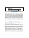
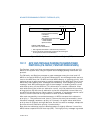
The trigger mode register (TMR) indicates the trigger mode of the interrupt (see
Figure 10-28). Upon acceptance of an interrupt into the IRR, the corresponding TMR
Figure 10-28. IRR, ISR and TMR Registers
255
0
Reserved
Addresses: IRR FEE0 0200H - FEE0 0270H
Value after reset: 0H
16 15
IRR
Reserved ISR
Reserved TMR
ISR FEE0 0100H - FEE0 0170H
TMR FEE0 0180H - FEE0 01F0H


