2-26 Vol. 3
SYSTEM ARCHITECTURE OVERVIEW
all interrupts are enabled. This field is available in 64-bit mode. A value of 15
means all interrupts will be disabled.
2.5.1 CPUID Qualification of Control Register Flags
The VME, PVI, TSD, DE, PSE, PAE, MCE, PGE, PCE, OSFXSR, and OSXMMEXCPT flags
in control register CR4 are model specific. All of these flags (except the PCE flag) can
be qualified with the CPUID instruction to determine if they are implemented on the
processor before they are used.
The CR8 register is available on processors that support Intel 64 architecture.
2.6 EXTENDED CONTROL REGISTERS (INCLUDING THE
XFEATURE_ENABLED_MASK REGISTER)
If CPUID.01H:ECX.XSAVE[bit 26] is 1, the processor supports one or more
extended control registers (XCRs). Currently, the only such register defined is
XCR0, the XFEATURE_ENABLED_MASK register. This register specifies the set of
processor states that the operating system enables on that processor, e.g. x87 FPU
States, SSE states, and other processor extended states that Intel 64 architecture
may introduce in the future. The OS programs XCR0 to reflect the features it
supports.
Software can access XCR0 only if CR4.OSXSAVE[bit 18] = 1. (This bit is also readable
as CPUID.01H:ECX.OSXSAVE[bit 27].) The layout of XCR0 is architected to allow
software to use CPUID leaf function 0DH to enumerate the set of bits that the
processor supports in XCR0 (see CPUID instruction in
Intel® 64 and IA-32 Architec-
tures Software Developer’s Manual, Volume 2A). Each processor state (X87 FPU
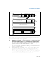
Figure 2-7. XFEATURE_ENABLED_MASK Register (XCR0)
63
x87 FPU/MMX state (must be 1)
Reserved for XCR0 bit vector expansion
Reserved / Future processor extended states
2
1
0
SSE state
Reserved (must be 0)
1


