6-2 Vol. 3
INTERRUPT AND EXCEPTION HANDLING
6.2 EXCEPTION AND INTERRUPT VECTORS
To aid in handling exceptions and interrupts, each architecturally defined exception
and each interrupt condition requiring special handling by the processor is assigned
a unique identification number, called a vector. The processor uses the vector
assigned to an exception or interrupt as an index into the interrupt descriptor table
(IDT). The table provides the entry point to an exception or interrupt handler (see
Section 6.10, “Interrupt Descriptor Table (IDT)”).
The allowable range for vector numbers is 0 to 255. Vectors in the range 0 through
31 are reserved by the Intel 64 and IA-32 architectures for architecture-defined
exceptions and interrupts. Not all of the vectors in this range have a currently defined
function. The unassigned vectors in this range are reserved. Do not use the reserved
vectors.
Vectors in the range 32 to 255 are designated as user-defined interrupts and are not
reserved by the Intel 64 and IA-32 architecture. These interrupts are generally
assigned to external I/O devices to enable those devices to send interrupts to the
processor through one of the external hardware interrupt mechanisms (see
Section
6.3, “Sources of Interrupts”).
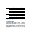
Table 6-1 shows vector assignments for architecturally defined exceptions and for the
NMI interrupt. This table gives the exception type (see Section 6.5, “Exception Clas-
sifications”) and indicates whether an error code is saved on the stack for the excep-
tion. The source of each predefined exception and the NMI interrupt is also given.
6.3 SOURCES OF INTERRUPTS
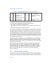
The processor receives interrupts from two sources:
• External (hardware generated) interrupts.
• Software-generated interrupts.
6.3.1 External Interrupts
External interrupts are received through pins on the processor or through the local
APIC. The primary interrupt pins on Pentium 4, Intel Xeon, P6 family, and Pentium
processors are the LINT[1:0] pins, which are connected to the local APIC (see
Chapter 10, “Advanced Programmable Interrupt Controller (APIC)”). When the local
APIC is enabled, the LINT[1:0] pins can be programmed through the APIC’s local
vector table (LVT) to be associated with any of the processor’s exception or interrupt
vectors.
When the local APIC is global/hardware disabled, these pins are configured as INTR
and NMI pins, respectively. Asserting the INTR pin signals the processor that an
external interrupt has occurred. The processor reads from the system bus the inter
-
rupt vector number provided by an external interrupt controller, such as an 8259A


