10-44 Vol. 3
ADVANCED PROGRAMMABLE INTERRUPT CONTROLLER (APIC)
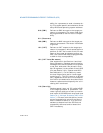
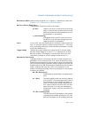
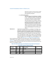
10.7.1.1 ICR Operation in x2APIC Mode
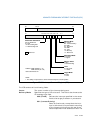
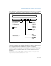
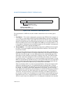
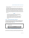
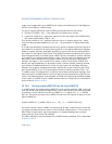
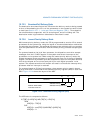
In x2APIC mode, the layout of the Interrupt Command Register is shown in Figure
10-17. The lower 32 bits of ICR in x2APIC mode is identical to the lower half of the
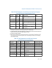
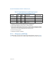
All excluding Self Valid Edge All Modes
1
X
All excluding Self Valid
2
Level Fixed, Lowest Priority
1
, NMI X
All excluding Self Invalid
5
Level SMI, Start-Up X
All excluding Self Valid
3
Level INIT X
X Invalid
5
Level SMI, Start-Up X
NOTES:
1. The ability of a processor to send a lowest priority IPI is model specific.
2. Treated as edge triggered if level bit is set to 1, otherwise ignored.
3. Treated as edge triggered when Level bit is set to 1; treated as “INIT Level Deassert” message
when level bit is set to 0 (deassert). Only INIT level deassert messages are allowed to have the
level bit set to 0. For all other messages the level bit must be set to 1.
4. X means the setting is ignored.
5. The behavior of the APIC is undefined.
Table 10-7 Valid Combinations for the P6 Family Processors’
Local APIC Interrupt Command Register (Contd.)
Destination
Shorthand
Valid/
Invalid
Trigger
Mode
Delivery Mode
Destination Mode


