Vol. 3 16-7
DEBUGGING, PROFILING BRANCHES AND TIME-STAMP COUNTER
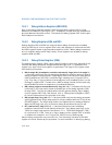
the lower address bits in the debug registers. Unaligned data or I/O breakpoint
addresses do not yield valid results.
A data breakpoint for reading or writing data is triggered if any of the bytes partici-
pating in an access is within the range defined by a breakpoint address register and
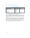
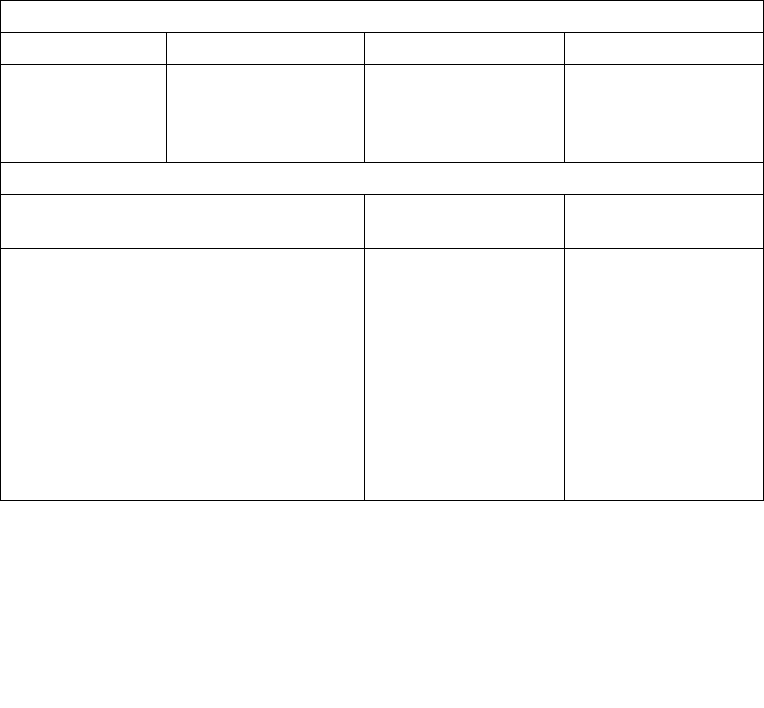
its LENn field. Table 16-1 provides an example setup of debug registers and data
accesses that would subsequently trap or not trap on the breakpoints.
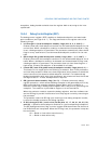
A data breakpoint for an unaligned operand can be constructed using two break-
points, where each breakpoint is byte-aligned and the two breakpoints together
cover the operand. The breakpoints generate exceptions only for the operand, not for
neighboring bytes.
Instruction breakpoint addresses must have a length specification of 1 byte (the
LENn field is set to 00). Code breakpoints for other operand sizes are undefined. The
processor recognizes an instruction breakpoint address only when it points to the
first byte of an instruction. If the instruction has prefixes, the breakpoint address
must point to the first prefix.
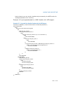
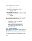
Table 16-1. Breakpoint Examples
Debug Register Setup
Debug Register R/Wn Breakpoint Address LENn
DR0
DR1
DR2
DR3
R/W0 = 11 (Read/Write)
R/W1 = 01 (Write)
R/W2 = 11 (Read/Write)
R/W3 = 01 (Write)
A0001H
A0002H
B0002H
C0000H
LEN0 = 00 (1 byte)
LEN1 = 00 (1 byte)
LEN2 = 01) (2 bytes)
LEN3 = 11 (4 bytes)
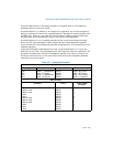
Data Accesses
Operation Address Access Length
(In Bytes)
Data operations that trap
- Read or write
- Read or write
- Write
- Write
- Read or write
- Read or write
- Read or write
- Write
- Write
- Write
A0001H
A0001H
A0002H
A0002H
B0001H
B0002H
B0002H
C0000H
C0001H
C0003H
1
2
1
2
4
1
2
4
2
1


