10-48 Vol. 3
ADVANCED PROGRAMMABLE INTERRUPT CONTROLLER (APIC)
The interpretation of MDA for the two models is described in the following para-
graphs.
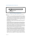
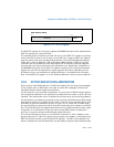
1. Flat Model — This model is selected by programming DFR bits 28 through 31 to
1111. Here, a unique logical APIC ID can be established for up to 8 local APICs by
setting a different bit in the logical APIC ID field of the LDR for each local APIC. A
group of local APICs can then be selected by setting one or more bits in the MDA.
Each local APIC performs a bit-wise AND of the MDA and its logical APIC ID. If a
true condition is detected, the local APIC accepts the IPI message. A broadcast to
all APICs is achieved by setting the MDA to 1s.
2. Cluster Model — This model is selected by programming DFR bits 28 through 31
to 0000. This model supports two basic destination schemes: flat cluster and
hierarchical cluster.
The flat cluster destination model is only supported for P6 family and Pentium
processors. Using this model, all APICs are assumed to be connected through the
APIC bus. Bits 28 through 31 of the MDA contains the encoded address of the
destination cluster and bits 24 through 27 identify up to four local APICs within
the cluster (each bit is assigned to one local APIC in the cluster, as in the flat
connection model). To identify one or more local APICs, bits 28 through 31 of the
MDA are compared with bits 28 through 31 of the LDR to determine if a local APIC
is part of the cluster. Bits 24 through 27 of the MDA are compared with Bits 24
through 27 of the LDR to identify a local APICs within the cluster.
Sets of processors within a cluster can be specified by writing the target cluster
address in bits 28 through 31 of the MDA and setting selected bits in bits 24
through 27 of the MDA, corresponding to the chosen members of the cluster. In
this mode, 15 clusters (with cluster addresses of 0 through 14) each having 4
local APICs can be specified in the message. For the P6 and Pentium processor’s
local APICs, however, the APIC arbitration ID supports only 15 APIC agents.
Therefore, the total number of processors and their local APICs supported in
this mode is limited to 15. Broadcast to all local APICs is achieved by setting all
destination bits to one. This guarantees a match on all clusters and selects all
APICs in each cluster. A broadcast IPI or I/O subsystem broadcast interrupt with
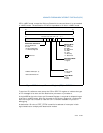
Figure 10-20. Destination Format Register (DFR)
31
0
Model
28
Reserved (All 1s)
Address: 0FEE0 00E0H
Value after reset: FFFF FFFFH
Flat model: 1111B
Cluster model: 0000B


