. . . . .
WORKING WITH THE CPU
MemoryManagement Unit (MMU)
www.digiembedded.com 107
MMU program
accessible
registers
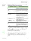
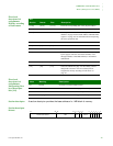
This table shows the CP15 registers that are used in conjunction with page table
descriptors stored in memory to determine MMU operation.
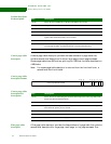
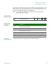
All CP15 MMU registers, except R8: TLB Operations, contain state that can be read
using
MRC instructions, and can be written using MCR instructions. Registers R5
(Fault Status) and R6 (Fault Address) are also written by the MMU during an abort.
Writing to R8: TLB Operations causes the MMU to perform a TLB operation, to
manipulate TLB entries. This register is write-only.
Address
translation
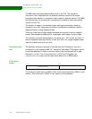
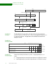
The virtual address (VA) generated by the CPU core is converted to a modified
virtual address (MVA) by the FCSE (fast context switch extension) using the value
held in CP15 R13: Process ID register. The MMU translates MVAs into physical
addresses to access external memory, and also performs access permission
checking.
Register Bits Description
R1: Control register M, A, S, R Contains bits to enable the MMU (M bit), enable data address
alignment checks (A bit), and to control the access protection
scheme (S bit and R bit).
R2: Translation Table Base
register
[31:14] Holds the physical address of the base of the translation table
maintained in main memory. This base address must be on a 16
KB boundary.
R3: Domain Access Control
register
[31:0] Comprises 16 two-bit fields. Each field defines the access
control attributes for one of 16 domains (D15 to D00).
R5: Fault Status registers,
IFSR and DFSR
[7:0] Indicates the cause of a data or prefetch abort, and the domain
number of the aborted access when an abort occurs. Bits [7:4]
specify which of the 16 domains (D15 to D00) was being
accessed when a fault occurred. Bits [3:0] indicate the type of
access being attempted. The value of all other bits is
UNPREDICTABLE. The encoding of these bits is shown in
“Priority encoding table” on page 120).
R6: Fault Address register [31:0] Holds the MVA associated with the access that caused the data
abort. See “Priority encoding table” on page 120 for details of
the address stored for each type of fault.
R8: TLB Operations
register
[31:0] Performs TLB maintenance operations. These are either
invalidating all the (unpreserved) entries in the TLB, or
invalidating a specific entry.
R10: TLB Lockdown
register
[28:26] and 0 Enables specific page table entries to be locked into the TLB.
Locking entries in the TLB guarantees that accesses to the
locked page or section can proceed without incurring the time
penalty of a TLB miss. This enables the execution latency for
time-critical pieces of code, such as interrupt handlers, to be
minimized.


