MEMORY CONTROLLER
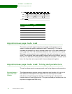
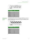
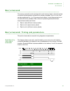
Bus turnaround: Timing and parameters
220 Hardware Reference NS9215
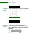
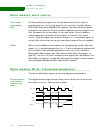
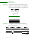
Write followed by
a read with no
turnaround
This diagram shows a zero wait write followed by a zero wait read with default
turnaround between the transfers of one cycle. Three wait states are added to the
write transfer; five wait states are added to the read transfer. The five AHB
arbitration cycles for the read transfer include two wait states to allow the previous
write access to complete and the three standard wait states for the read transfer.
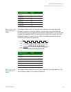
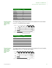
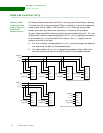
Read followed by
a write with two
turnaround cycles
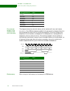
TIs diagram shows a zero wait read followed by a zero wait write with two
turnaround cycles added. The standard minimum of three AHB arbitration cycles is
added to the read transfer and two wait states are added to the write transfer (as
for any read-write transfer sequence).
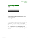
Timing parameter Value
WAITRD 0
WAITOEN 0
WAITPAGE N/A
WAITWR 0
WAITWEN 0
WAITTURN 0
B0A
D(B)D(A)
cs[n]
st_we_n
st_oe_n
clk_out
addr
data
st_oe_n
st_we_n
cs[n]
clk_out
addr
data
B
A
0
D(A) D(B)


