SERIAL CONTROL MODULE: HDLC
Clocking
416 Hardware Reference NS9215
Receive operation In the receiver, each byte is marked with status to indicate end-of-frame, short
frame, and CRC error. The receiver automatically synchronizes on flag bytes, and
presets the CRC checker accordingly. If the current receive frame is not needed (for
example, because it is addressed to a different station), a flag search command is
available. The flag search command forces the receiver to ignore the incoming data
stream until another flag is received.
Transmit
operation
In the transmitter, the CRC generator is preset and the opening flag transmitted
automatically after the first byte is written to the transmitter buffer. The CRC an the
closing flag are transmitted after the byte that is written to the buffer through the
Address register. If no CRC is required, writing the last byte of the frame to the Long
Stop register automatically appends a closing flag after the last byte.
Transmitter
underflow
If the transmitter underflows, either an abort or a flag is transmitted, under software
control. There is a command available to send the abort pattern (seven consecutive
ones) if a transmit frame needs to be aborted prematurely. The abort command takes
effect on the next byte boundary and causes an FEh (a zero followed by seven ones)
transmission, after which the transmitter sends the idle line condition. The abort
command also purges the transmit FIFO The idle line condition can be either flags or
all ones.
. . . . . . . . . . . . . . . . . . . . . . . . . . . . . . . . . . . . . . . . . . . . . . . . . . . . . . . . . . . . . . . . . . . . . . . . . . . . . . . . . .
Clocking
A 15-bit divider circuit provides the clocking for the HDLC module. This clock is
sixteen times the data rate. The receiver uses a digital phase locked loop (DPLL) to
generate a synchronized receive clock for the incoming data stream. The HDLC
module also allows for an external 1x (same speed as the data rate) clock for both
the receiver and the transmitter.
HDLC receive and transmit clocks can be input or output. When using an external
clock, the maximum data rate is one-sixth of the 29.4912 MHz reference clock rate,
or 4.9152 Mbps.
. . . . . . . . . . . . . . . . . . . . . . . . . . . . . . . . . . . . . . . . . . . . . . . . . . . . . . . . . . . . . . . . . . . . . . . . . . . . . . . . . .
Bits
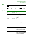
The transmitter cannot send an arbitrary number of bits, but only a multiple of
bytes. The receiver, however, can receive frames of any bit length. If the last
“byte” in the frame is not eight bits, the receiver sets a status flag that is buffered
along with this last byte. Software then uses the table shown next to determine the
number of valid data bits in this last “byte.” Note that the receiver transfers all bits


