. . . . .
PINOUT (265)
System mode
www.digiembedded.com 45
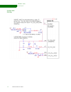
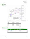
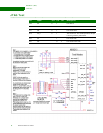
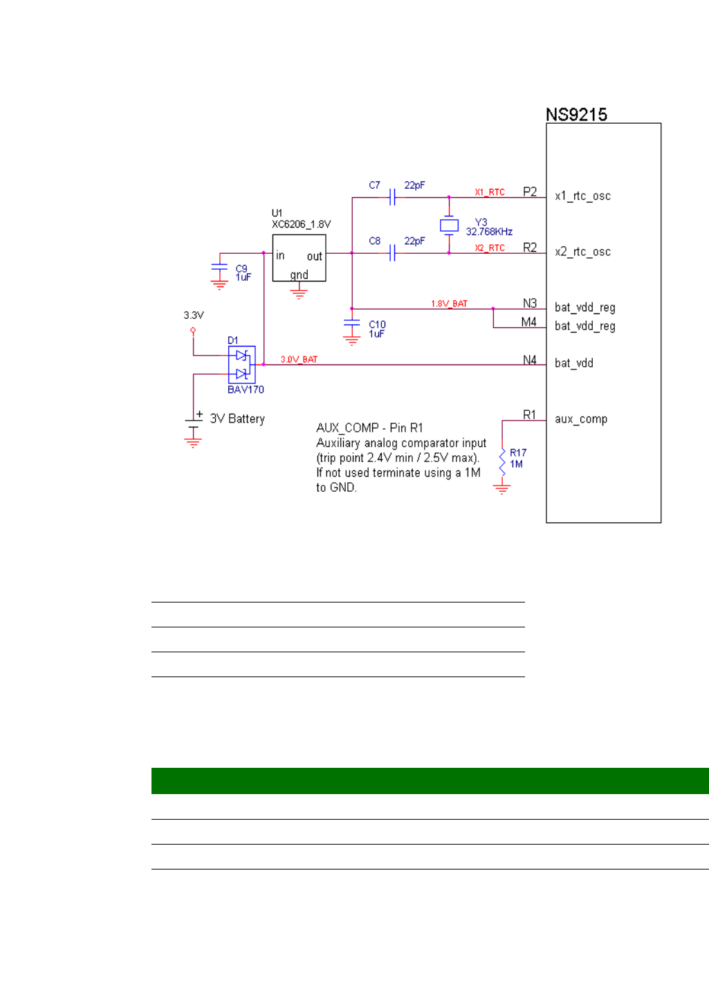
RTC clock and
battery backup
drawing
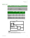
Note: If RTC battery backup is not used, the following connection changes can be
made.
. . . . . . . . . . . . . . . . . . . . . . . . . . . . . . . . . . . . . . . . . . . . . . . . . . . . . . . . . . . . . . . . . . . . . . . . . . . . . . . . . .
System mode
v
N3, M4 bat_vdd_reg tie to 1.8V
32.788kHz crystal load capacitors tie to N3, M4 (1.8V)
N4 bat_vdd tie to 3.3V
R1 aux_comp tie to ground
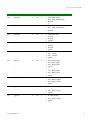
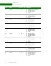
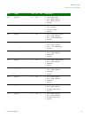
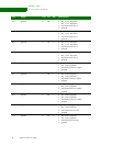
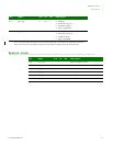
Pin Signal U/D I/O OD Description
M13 sys_mode_2 I test mode pins
M14 sys_mode_1 I test mode pins
L14 sys_mode_0 I test mode pins


