. . . . .
SYSTEM CONTROL MODULE
Bootstrap initialization
www.digiembedded.com 153
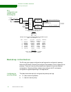
Pin name Configuration bits
gpio_a[3] Endian configuration
0 Little endian
1Big endian
gpio_a[2] Boot mode
0 Boot from SDRAM using serial SPI EEPROM
1 Boot from Flash ROM
gpio_a[0], addr[23] Flash/SPI configuration
If booting from Flash:
00 8 bit
01 32 bit
10 32 bit
11 16 bit
If booting from SPI
00 Reserved
01 8-bit addressing
10 24-bit addressing
11 16-bit addressing
addr[19:9] Gen ID
addr[7] PLL bypass setting
0 Bypass
1 Normal operation
addr[6:5] PLL output divider setting OD
00 3
01 2
10 1
11 0
addr[4:0] PLL reference clock divider setting NR
00111 31 01100 20 10001 9
00110 30 01011 19 10000 8
00101 29 01010 18 11111 7
00100 28 01001 17 11110 6
00011 27 01000 16 11101 5
00010 26 10111 15 11100 4
00001 25 10110 14 11011 3
00000 24 10101 13 11010 2
01111 23 10100 12 11001 1
01110 22 10011 11 11000 0
01101 21 10010 10


