


SYSTEM CONTROL MODULE
System bus arbiter
138 Hardware Reference NS9215
. . . . . . . . . . . . . . . . . . . . . . . . . . . . . . . . . . . . . . . . . . . . . . . . . . . . . . . . . . . . . . . . . . . . . . . . . . . . . . . . . .
System bus arbiter
The bus arbitration mechanism ensures that only one bus master has access to the
system bus at any time. If you are using a system in which bus bandwidth allocation
is critical, you must be sure that your worst-case bus bandwidth allocation goals can
be met. See “Arbiter configuration example” on page 140 for information about
configuring the AHB arbiter.
High speed bus
system
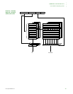
The high-speed bus system is split into two subsystems:
High-speed peripheral subsystem: Connects all high-speed peripheral devices
to a port on the external memory controller.
CPU subsystem: Connects the CPU directly to a second port on the external
memory controller.
High-speed bus
arbiters
The high-speed bus contains two arbiters: one for the ARM926 (CPU) and one for the
main bus.
CPU arbiter. Splits the bandwidth 50–50 between the data and instruction
interfaces. If the CPU access is to external memory, no further arbitration is
necessary; the CPU has immediate access to external memory through slave
port 0 on the memory controller. If CPU access is to one of the peripherals on
the main bus, however, the main arbiter will arbitrate the access.
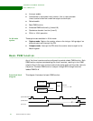
Main arbiter. Contains a 16-entry Bus Request Configuration (BRC) register.
Each BRC entry represents a bus request and grant channel. Each
request/grant channel can be assigned to only one bus master at a time. Each
bus master can be connected to multiple request/grant channels
simultaneously, however, depending on the bus bandwidth requirement of that
master.
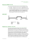
Each request/grant channel has a two-bit Bandwidth Reduction Field (BRF)
to determine how often each channel can arbitrate for the system bus —
100%, 75%, 50%, or 25%. A BRF value of 25%, for example, causes a channel
to be skipped every 3 or 4 cycles. The BRC gates the bus requesting signals
going into a 16-entry Bus Request register (BRR). As a default, unassigned
channels in the BRC block the corresponding BRR entries from being set by
any bus request signals. On powerup, only the CPU is assigned to one of the
channels with 100% bandwidth strength as the default setting.
How the bus
arbiter works
1 The arbiter evaluates the BRR at every bus clock until one or more bus requests
are registered.