. . . . .
SYSTEM CONTROL MODULE
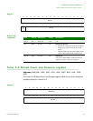
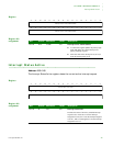
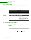
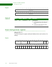
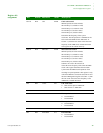
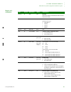
Clock Configuration register
www.digiembedded.com 181
Register bit
assignment
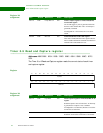
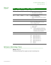
Bits Access Mnemonic Reset Description
D31:29 R/W CSC 0x000 Clock scale control
000 Full speed (149.9136/74.9568)
001 Divide by 2 (74.9568/37.4784)
010 Divide by 4 (37.4784/18.7392)
011 Divide by 8 (18.7393/9.3693)
100 Divide by 16 (9.3693/4.6848)
Determines the frequency of the system
clock rates. The full speed rate is 150MHz for the
CPU clock and 75MHz for the AHB clock. If
CCSEL = 0, then the CPU clock will be the same
frequency as the AHB clock, 74.9568 maximum.
This register can be written on the fly.
D28:26 R/W Max CSC 0x000 Max clock scale control
000 Full speed (149.9136/74.9568)
001 Divide by 2 (74.9568/37.4784)
010 Divide by 4 (37.4784/18.7392)
011 Divide by 8 (18.7393/9.3693)
100 Divide by 16 (9.3693/4.6848)
Software can write to the CSC bits to
reduce the clock frequency of the CPU and AHB
clocks. This register determines the maximum
system CPU and AHB clock frequencies when
returning low speed operation. This register is only
valid if the hardware clock scale control bit is set in
the Power Management register. If CCSEL = 0, then
the CPU clock will be the same frequency as the
AHB clock, 74.9568 maximum.
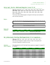
D25 R/W CCSel 0x0 CPU clock select
0 CPU clock is equal to AHB clock
1 CPU clock is 2 x AHB clock
D24:18 N/A Reserved N/A N/A
D17 R/W MCOut 1 0x1 Memory clock out 1
0 Clock disabled
1 Clock enabled
D16 R/W MCOut 0 0x1 Memory clock out 0
0 Clock disabled
1 Clock enabled
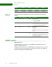
D15 N/A Reserved N/A N/A
D14 R/W EXT DMA 0x1 External DMA
0 Clock disabled
1 Clock enabled


