


I2C MASTER/SLAVE INTERFACE
I2C external addresses
448 Hardware Reference NS9215
serial clock. Serial clock modulation can be controlled by both the
transmitter and receiver, based in their hosts’ service speed.
Multi-master bus The I
2
C is a true multi-master bus with collision detection and arbitration to
prevent data corruption when two or more masters initiate transfer simultaneously.
If a master loses arbitration during the addressing stage, it is possible that the
winning master is trying to address the transfer. The losing master must therefore
immediately switch over to its slave mode.
The on-chip filtering rejects spikes on the bus data line to preserve data integrity.
The number of ICs that can be connected to the same bus is limited only by a
maximum bus capacity of 400 pf.
. . . . . . . . . . . . . . . . . . . . . . . . . . . . . . . . . . . . . . . . . . . . . . . . . . . . . . . . . . . . . . . . . . . . . . . . . . . . . . . . . .
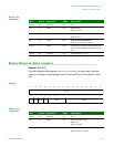
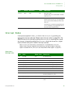
I
2
C external addresses
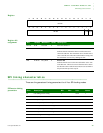
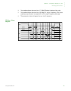
I
2
C external [bus] addresses are allocated as two groups of eight addresses (0000XXX
and
1111XXX)
:
The general call address is for addressing all devices connected to the I
2
C bus. A
device can ignore this address by not issuing an acknowledgement. The meaning of
the general call address is always specified in the second byte.
Slave
addres
R/W
bit
Description
0000 000 0
General call address
0000 000 1 START byte (not supported in the processor)
0000 001 X CBUS address (not supported in the processor)
0000 010 X Reserved for different bus format
0000 011 X Reserved
0000 1xx X hs-mode master code (not supported in the
processor)
1111 1xx X Reserved
1111 0xx X 10-bit slave address