


SYSTEM CONTROL MODULE
Bootstrap initialization
152 Hardware Reference NS9215
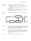
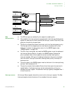
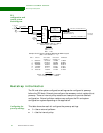
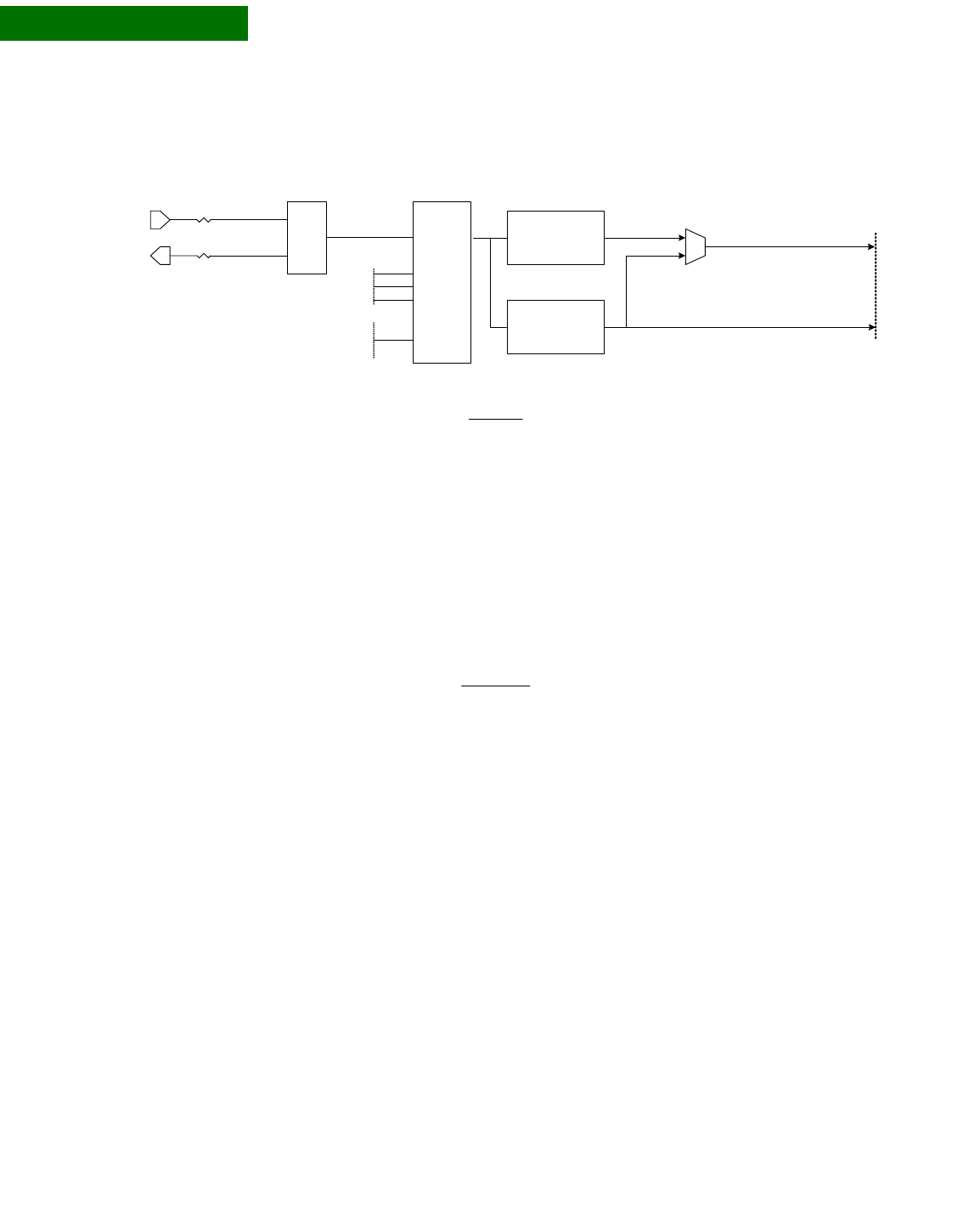
PLL
configuration and
control system
block diagram
. . . . . . . . . . . . . . . . . . . . . . . . . . . . . . . . . . . . . . . . . . . . . . . . . . . . . . . . . . . . . . . . . . . . . . . . . . . . . . . . . .
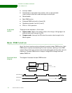
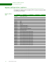
Bootstrap initialization
The PLL and other system configuration settings can be configured at powerup
before the CPU boots. External pins configure the necessary control register bits at
powerup. There are internal pullup resistors on these pins to provide a default
configuration. External pulldown resistors can configure the PLL and system
configuration registers depending on the application.
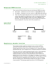
Configuring the
powerup settings
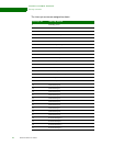
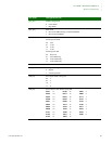
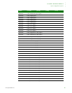
This table shows how each bit configures the powerup settings.
0 = Use an external pulldown
1 = Use the internal pullup
NR+1 Clk Out CPU clock CPU clock AHB clock
(CCSel = 1) (CCSel = 0)
6 299.8272 149.9136 74.9568 74.9568
7 256.9947 128.4975 64.2487 64.2487
8 224.8704 112.4352 56.2176 56.2176
9 199.8848 99.9424 49.9712 49.9712
10 179.8962 89.9482 44.9741 44.9741
11 163.5421 81.7711 40.8855 40.8855
12 149.9136 74.9568 37.4784 37.4784
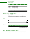
PLL
Ref
Clk
Clk
Out
NR[4:0]
PLL Vco = (RefClk / NR+1) * (NF+1)
ClkOut = PLL Vco / OD+1
defaults
NR + 1 = 8
OD + 1 = 1
NF + 1 = 61
set by
strapping
or software
OSC
BP
29.4912 MHz
x1_sys_osc
x2_sys_osc
div by
2,4,8,16,32,64,
128
(programmable)
div by
4,8,16,32,64,128
or 256
(programmable)
CPU clock (149.9136 MHz max)
AHB clocks (74.9569MHz max)
main clocks
to modules
NF[8:0]
set by
software
only
OD[1:0]
Sample Clock Frequency Settings With 29.4912MHz Crystal
(NF+1 = 61 and OD + 1 = 1)
Restrictions
RefClk / NR+1 range: 275KHz – 550MHz
PLL Vco range: 110MHz – 550MHz
mux select default is
AHB clock (CCSel = 0)