


SYSTEM CONTROL MODULE
PLL Configuration register
186 Hardware Reference NS9215
. . . . . . . . . . . . . . . . . . . . . . . . . . . . . . . . . . . . . . . . . . . . . . . . . . . . . . . . . . . . . . . . . . . . . . . . . . . . . . . . . .
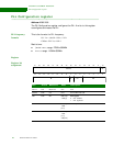
PLL Configuration register
Address: A090 0188
The PLL Configuration register configures the PLL. A write to this register
reconfigures and resets the PLL.
PLL frequency
formula
This is the formula for PLL frequency:
PLL Vco = (RefClk / NR+1) * NF+1
ClkOut = PLL Vco / OD+1
Restrictions:
(RefClk / NR+1) range: 275KHz–550MHz
PLL Vco range: 110MHz–550MHz
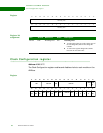
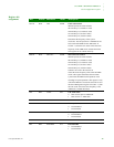
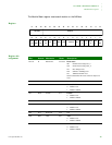
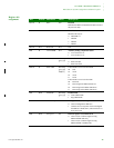
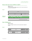
Register
Register bit
assignment
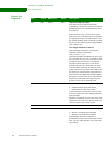
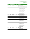
Bits Access Mnemonic Reset Description
D31:17 N/A Reserved N/A N/A
D16:08 R/W NF 0x3c PLL feedback divider
D07 R/W BP HW strap
~addr[7]
PLL bypass
0 PLL enabled
1 PLL bypassed
D06:05 R/W OD HW strap
~addr
[6:5]
PLL output divider
D04:00 R/W NR HW strap
~addr
[4:3],
addr[2:0]
PLL reference clock divider
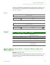
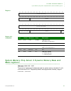
13121110987654321015 14
31 29 28 27 26 25 24 23 22 21 20 19 18 17 1630
NF
Reserved
NR
NF
BP
OD